Why Zeolites Are Nature’s Ion Exchangers
To understand why zeolites can perform ion exchange at all, you need to start with what they are — not just chemically, but architecturally.
Zeolites are crystalline aluminosilicate minerals built from corner-sharing (Si,Al)O₄ tetrahedra. These tetrahedra link into a three-dimensional framework containing an intricate network of channels and cages, with pore openings typically ranging from 0.3 to 0.8 nanometers. The International Zeolite Association recognizes over 250 distinct framework types, each identified by a three-letter code. The most industrially significant are LTA (Zeolite A), FAU (Zeolites X and Y), MOR (mordenite), and HEU (heulandite/clinoptilolite).
Ion exchange becomes possible because of what happens when aluminum replaces silicon in the framework. Silicon is tetravalent (Si⁴⁺), but aluminum is trivalent (Al³⁺). Every time an Al³⁺ substitutes for a Si⁴⁺ in the tetrahedral lattice, the framework acquires one net negative charge. These negative charges must be balanced by extra-framework cations — typically Na⁺, K⁺, Ca²⁺, or Mg²⁺ — that sit loosely inside the channels and cages, hydrated and mobile. The general zeolite formula captures this arrangement: Mⁿ⁺₁/ₙ(AlO₂)⁻(SiO₂)ₓ·yH₂O.
Picture the zeolite framework as a honeycomb wall studded with negative “hooks.” The balancing cations hang on those hooks, held in place by electrostatic attraction but not chemically bonded to the framework itself. They can be pried off and replaced by other cations from a surrounding solution. The wall stays intact. Only the “hooks” change hands. That is zeolite ion exchange.
The Si/Al ratio directly governs how many exchange sites a given zeolite offers. A zeolite with Si/Al = 1 (like Na-A, LTA) carries the maximum possible framework charge: roughly one cation site per tetrahedron. As the Si/Al ratio rises, the density of negative charge on the framework drops proportionally, and with it the ion exchange capacity. At the far end of the spectrum, pure-silica zeolites (Si/Al → ∞) have essentially zero ion exchange capacity. This relationship between framework composition and exchange capacity is the first design lever that makes zeolites so versatile. You tune the number of exchange sites by controlling the synthesis chemistry.
How the Zeolite Ion Exchange Process Works
The ion exchange process in zeolites is not a single instantaneous event. It is a multi-step physical-chemical sequence governed by three layers of control: spatial accessibility (which ions can physically reach the sites), thermodynamic selectivity (which ions the framework prefers to bind), and kinetic diffusion (how fast the exchange proceeds). Understanding each layer separately reveals why seemingly similar zeolites can behave completely differently in the same application.
The Ion Exchange Sites — Where Exchange Happens
Not all cations in a zeolite are created equal. Within the framework, crystallographically distinct positions — designated Site I, I′, II, II′, III, and so on — offer different local coordination environments and different degrees of accessibility to incoming ions.
In a typical LTA-type zeolite (Zeolite A), Na⁺ cations occupy multiple sites: Site I deep inside the hexagonal prism, Site I′ inside the β-cage (sodalite cage), and Sites II and III in the larger α-cage near the six- and eight-membered oxygen rings. The critical point for practical ion exchange: not all of these sites are accessible. Site I′ cations, buried inside the β-cage behind a six-ring aperture of only ~2.2 Å, cannot be reached by most hydrated cations. Their hydrated radii are considerably larger: Na⁺ at ~3.6 Å, Ca²⁺ at ~4.1 Å, K⁺ at ~3.3 Å. Only cations occupying accessible sites — predominantly in the α-cage — participate in exchange under normal conditions.
This distinction between total cations and accessible cations is why the theoretical cation exchange capacity (calculated from framework Al content) invariably exceeds the effective CEC measured in practice. It also explains why pore architecture matters as much as chemical composition. An FAU-type zeolite (Zeolite X/Y) with its 12-ring pore openings (~7.4 Å) makes more cation sites physically reachable than an LTA-type with 8-ring openings (~4.1 Å), even if both have similar Si/Al ratios.
The Exchange Process — Step by Step
For a cation to move from an aqueous solution into a zeolite exchange site, it must complete a four-stage journey:
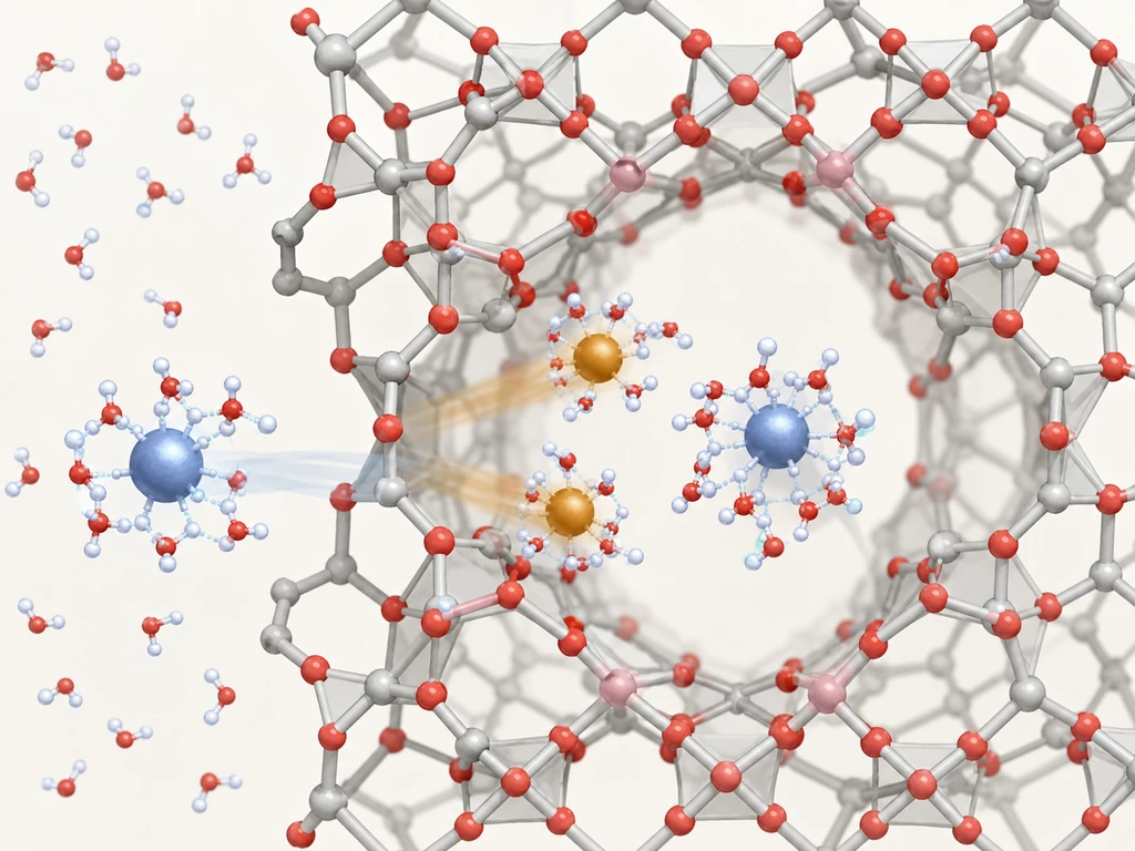
Step 1 — Film diffusion. The hydrated cation diffuses through the stagnant liquid film surrounding each zeolite particle to reach the external surface. This step is relatively fast under stirring, but can become rate-limiting at very low solution concentrations or with very fine particles.
Step 2 — Intraparticle diffusion. The cation enters the zeolite pore network and migrates through the channels toward an exchange site. This is typically the rate-controlling step of the entire process. Reported solid-phase diffusion coefficients are typically 10⁻⁹ to 10⁻¹⁰ cm²/s in batch systems, while apparent values in fixed beds can reach 10⁻⁸ to 10⁻⁹ cm²/s because interparticle transport also contributes. Zeolite particle size therefore has a disproportionate effect on exchange kinetics: halving the particle diameter cuts the intraparticle diffusion path length in half, roughly quadrupling the effective exchange rate.
Step 3 — Chemical exchange. At the site, the incoming cation displaces the resident cation through a direct ion-for-ion swap. This step itself is fast. The process is not limited by the chemistry of the exchange reaction but by the transport steps that feed it.
Step 4 — Reverse diffusion. The displaced cation makes the same journey in reverse, diffusing out of the zeolite and into the bulk solution to maintain charge balance.
Cation reaches particle surface
Migration through pore channels
Ion-for-ion swap at the site
Displaced cation exits to solution
This sequence explains a practical observation that often puzzles newcomers. A zeolite with excellent equilibrium selectivity for a target ion may still perform poorly in a flow-through column if the particle size is too large — because kinetics, not thermodynamics, dominates the contact-time-limited scenario. Researchers distinguish between film-diffusion-controlled systems (low concentration, small particles, poor mixing) and particle-diffusion-controlled systems (high concentration, larger particles) using standard kinetic models. The pseudo-first-order and pseudo-second-order equations have become the default tools for fitting zeolite ion exchange rate data in the literature.
What Determines Which Ions Get Exchanged
Given a mixture of cations competing for the same zeolite, which ones win? Three factors interact.
Charge density of the incoming cation. All else being equal, cations with higher charge density — high valence combined with small hydrated radius — experience stronger electrostatic attraction to the negatively charged framework. A divalent Ca²⁺ outcompetes monovalent Na⁺; a small, highly polarizing Pb²⁺ outcompetes a larger Sr²⁺. But this trend is not absolute, because selectivity also depends on…
The framework’s own charge density (Si/Al ratio). Low-silica zeolites (Si/Al ≈ 1–2), with their dense arrangement of negative framework charges, act as strong electrostatic fields and preferentially select high-charge-density cations. High-silica zeolites (Si/Al > 5), with sparser charge distribution, exhibit different — often reversed — selectivity patterns. The same cation pair can have completely different separation factors on Zeolite A (Si/Al=1) versus ZSM-5 (Si/Al>10).
Solution-phase competition. Concentration matters: a cation present at 100× the concentration of a more selective competitor can overwhelm the thermodynamic preference. So does pH. At low pH, H₃O⁺ competes for exchange sites; at high pH, many heavy metals hydrolyze or precipitate, removing themselves from the ion exchange equation.
The classic Ames (1960) selectivity sequence for natural clinoptilolite (HEU framework) is: Cs⁺ > Rb⁺ > K⁺ > NH₄⁺ > Ba²⁺ > Sr²⁺ > Na⁺ ≈ Ca²⁺ > Fe³⁺ > Al³⁺ > Mg²⁺ ≈ Li⁺. This sequence explains why clinoptilolite is widely used for removing radioactive cesium from contaminated water and why it performs well for ammonium removal but poorly for lithium recovery. The order is not universal: deposit origin, temperature, solution composition, and competing ions can shift the relative preference; at elevated temperatures, for example, NH₄⁺ may rank ahead of K⁺.
Cation Exchange Capacity — Measuring What Matters
Cation exchange capacity (CEC) is the single number that quantifies a zeolite’s ion exchange capability. It represents the maximum quantity of cations — expressed in milliequivalents per gram (meq/g) — that one gram of zeolite can exchange under defined conditions. A higher CEC means more exchange sites per unit mass, which translates to longer service cycles between regenerations in a column operation.
CEC Values Across Zeolite Types — A Comparative View
Different zeolite frameworks offer dramatically different CEC values, driven primarily by their Si/Al ratio:
| Zeolite Type | Framework Code | Typical Si/Al | Theoretical CEC (meq/g) | Typical Exchange Cation | Key Characteristic |
|---|---|---|---|---|---|
| Zeolite Na-A | LTA | 1.0 | 5.4 | Na⁺ | Highest CEC among commercial zeolites; narrow pores (8-ring) limit access for large hydrated cations |
| Zeolite Na-X | FAU | 1.0–1.5 | 3.8–4.8 | Na⁺ | Large pore (12-ring) enables access to more sites; workhorse for gas separation and water softening |
| Natural Clinoptilolite | HEU | 4.0–5.5 | 1.5–2.5 | Na⁺, K⁺, Ca²⁺ | Lower CEC but excellent selectivity for Cs⁺, NH₄⁺; acid-resistant, low cost |
| Natural Mordenite | MOR | 5.0–10.0 | 1.0–2.0 | Na⁺, Ca²⁺ | Narrow channels; effective for small cations and gas separations |
The headline numbers reveal an important trade-off. The highest-CEC zeolites (Na-A, Na-X) are also the least chemically stable in acidic environments: their aluminum-rich frameworks are susceptible to acid attack, where protons replace framework Al³⁺ and collapse the structure. Natural zeolites like clinoptilolite, with their higher Si/Al ratios and correspondingly lower CEC, tolerate pH conditions that would destroy a synthetic LTA or low-silica FAU zeolite within hours. In practical terms, you wouldn’t pack a Na-A column to treat acid mine drainage (pH 2–4), even though its CEC is more than double that of clinoptilolite. The framework simply wouldn’t survive.
How CEC Is Measured — Methods and What Can Go Wrong
CEC is not a single, universally standardized measurement. Two methods dominate, and understanding their differences matters whenever you compare data sheets from different zeolite suppliers.
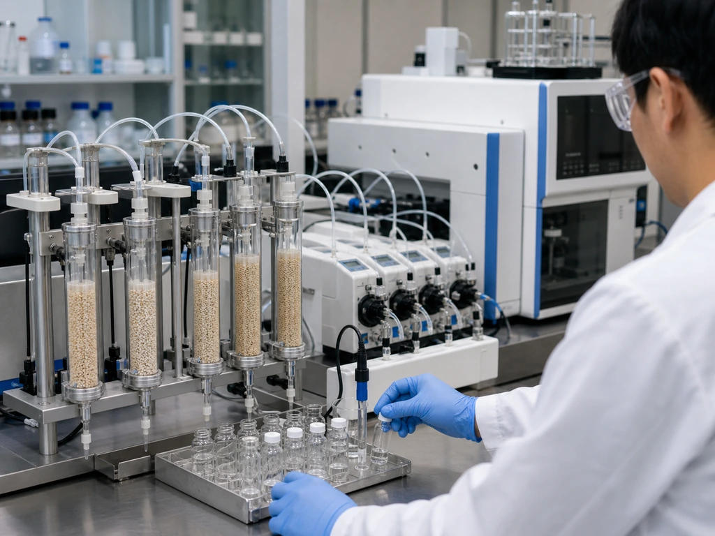
The ammonium acetate method (basis of ASTM D7503 and ISO 13536 frameworks) saturates the zeolite with NH₄⁺ ions from a buffered ammonium acetate solution (typically at pH 7), then displaces and measures the exchanged NH₄⁺. It works well for neutral to slightly alkaline conditions but loses accuracy at low pH, where H₃O⁺ competes with NH₄⁺ for exchange sites.
The cross-exchange method takes a more rigorous approach. Run a complete Na⁺ → K⁺ forward exchange (typically 10 cycles with 1M KCl at 40°C), measure total Na⁺ released, then run the reverse K⁺ → Na⁺ exchange, measure total K⁺ released, and take the average of the two values. When both directions agree within 0.4% absolute deviation — a quality-control benchmark in industrial zeolite production — the result is considered reliable.
Where Zeolite Ion Exchange Delivers Industrial Value
The mechanism and the metrics matter because they translate into real-world performance across a growing range of industrial and environmental applications. Zeolite ion exchange applications cluster into three categories: water-phase ion removal, environmental contaminant fixation, and — as explored in the following section — zeolite product engineering through cation modification.
Water Softening and Heavy Metal Removal
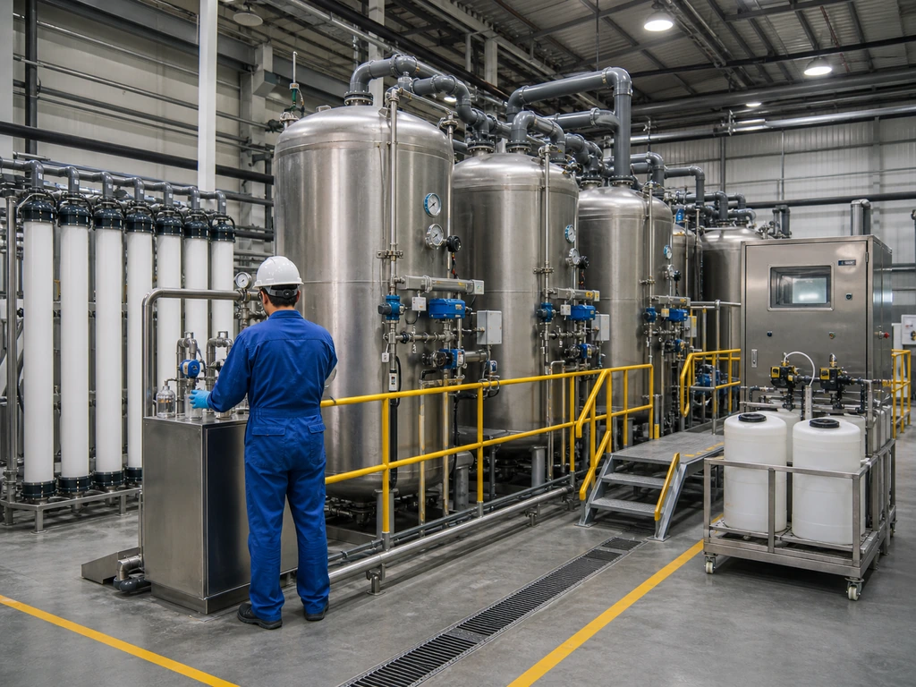
Water softening is the largest-volume application of zeolite ion exchange. The process is straightforward: a sodium-form zeolite (typically Na-A or Na-X) contacts hard water containing dissolved Ca²⁺ and Mg²⁺. The zeolite preferentially sorbs the divalent hardness ions and releases two Na⁺ ions for each Ca²⁺ or Mg²⁺ captured:
2Na⁺-Zeolite + Ca²⁺(aq) → Ca²⁺-Zeolite + 2Na⁺(aq)
Unlike the older lime-soda softening method, which produces calcium carbonate sludge that requires disposal, zeolite softening generates no solid waste stream. The only outputs are softened water and, eventually, a spent brine from regeneration. A saturated zeolite bed is regenerated by passing a concentrated NaCl solution (typically 1–3 M) through it, driving the exchange equilibrium in reverse. Regeneration efficiency with NaCl typically reaches 90–98%, with minimal capacity loss over multiple cycles when pH, salt concentration, contact time, and rinsing are maintained within the design range.
For heavy metal removal, zeolite performance depends strongly on mineral origin, pretreatment, particle size, pH, initial concentration, contact time, and competing ions. In a peer-reviewed study, heat-treated clinoptilolite achieved 98% copper removal, 88% lead removal, and 83% cadmium removal under the reported test conditions (Kuldeyev et al., Water, 2023). These results demonstrate the material’s potential, but they should not be treated as universal design values; representative-feed column or batch testing remains necessary before scale-up.
Removal
Removal
Removal
Removal
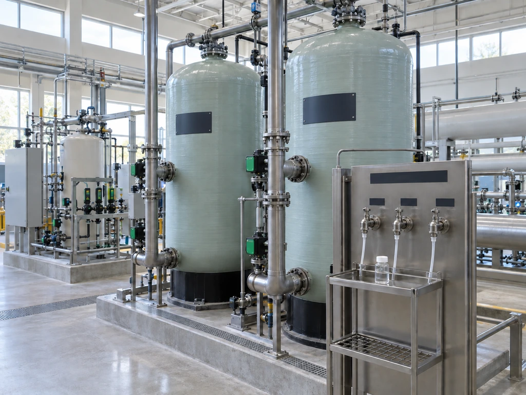
The practical engineering considerations for column-based systems are well-established. Typical operating parameters include space velocities of 2–10 bed volumes per hour and zeolite particle sizes of 0.5–2 mm (balancing low pressure drop against fast kinetics). Operators monitor the breakthrough curve — the S-shaped plot of outlet concentration vs. time — to track when the bed approaches saturation. The breakthrough point (typically C/C₀ = 0.1) triggers regeneration; the exhaustion point (C/C₀ = 0.9) means the bed is fully spent. One of the most dramatic real-world demonstrations of zeolite ion exchange at scale came after the 2011 Fukushima Daiichi accident, when sandbags filled with natural zeolite were placed at the intake screen rooms of Units 1–4 to adsorb radioactive cesium before it could diffuse offshore. That emergency response exploited precisely the Cs⁺ selectivity that places cesium at the top of clinoptilolite’s preference sequence.
Ammonium Removal and Environmental Remediation
Beyond heavy metals, zeolite ion exchange addresses two growing environmental challenges: nitrogen pollution and radionuclide containment.
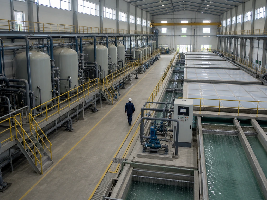
Municipal wastewater treatment plants increasingly face tightening discharge limits for ammonia-nitrogen. Clinoptilolite offers a compelling solution because NH₄⁺ sits high in its selectivity sequence — just behind K⁺. Typical ammonium exchange capacities for clinoptilolite range from 10 to 30 mg NH₄⁺ per gram of zeolite (ScienceDirect, 2024), with the exchange process operating effectively across the pH 4–8 range typical of secondary effluent. One significant practical consideration: potassium ions compete directly with ammonium for the same sites. In wastewaters with elevated K⁺ levels (for example, from certain food-processing operations), the effective ammonium capacity can drop by 30–50%.
For radionuclide containment, zeolites occupy a specialized niche where their combination of ion selectivity and radiation stability gives them advantages that no organic resin can match. The distribution coefficient (Kd) for Cs⁺ on clinoptilolite reaches 10³–10⁴ mL/g. A small amount of zeolite can strip cesium from large volumes of contaminated water down to parts-per-billion levels. This capability has been deployed at nuclear sites from Sellafield (UK) to Hanford (USA) to Fukushima (Japan), where zeolite ion exchange columns serve as the final polishing step in radioactive wastewater treatment trains.
Ion Exchange as a Manufacturing Tool — Engineering Zeolites for Performance
Most discussions of zeolite ion exchange treat it exclusively as an application — something zeolites do to treat water or capture contaminants. But ion exchange is equally important as a manufacturing process: a deliberate, controlled step that transforms a single zeolite framework into an entire family of functionally distinct products.
The concept is simple in principle. Synthesize the zeolite in its sodium form (the default for most hydrothermal syntheses), then use ion exchange to replace Na⁺ with a different cation that imparts specific performance characteristics. The framework itself — the LTA, FAU, or MFI architecture — remains unchanged. Only the “active species” inside the pores changes. One framework, multiple products.
| Zeolite Base | Exchanged Cation | Replaces | Purpose of Modification | Industrial Product Example |
|---|---|---|---|---|
| Na-X (FAU) | Li⁺ | Na⁺ | Enhance N₂ adsorption selectivity for air separation | LiLSX — PSA/VPSA oxygen concentrators |
| Na-X (FAU) | Ca²⁺ | Na⁺ | Adjust pore electrostatics for CO₂ and H₂O removal | CaX — cryogenic air separation pre-purification |
| Na-A (LTA) | K⁺ | Na⁺ | Narrow effective pore to ~3 Å | 3A molecular sieve — ethanol dehydration |
| Na-A (LTA) | Ca²⁺ | Na⁺ | Widen effective pore to ~5 Å | 5A molecular sieve — n-paraffin separation |
| Na-X (FAU) | Ag⁺ | Na⁺ | Create strong specific interaction with H₂ | Ag-zeolite — cryogenic tank vacuum insulation |
Each row in this table describes the same fundamental ion exchange mechanism discussed throughout this article — but executed in a manufacturing reactor under precisely controlled conditions, not in a wastewater tank. The difference between “scientific possibility” and “industrial product” lies in achieving high exchange degrees (typically >95%) without damaging the zeolite framework. This is a non-trivial challenge when exchanging highly charged or hydrolyzable cations at industrial scale.
Supplier qualification should focus on measurable evidence rather than broad capability claims. Request the target cation form and exchange degree, residual-salt limits, washing and activation conditions, framework integrity data, adsorption or catalytic performance results, and per-batch certificates with actual measured values. For a custom grade, confirm that the supplier can reproduce the selected exchange route at production scale and validate it against the intended feed and operating conditions.
JALON can support cation-exchanged zeolite development from exchange-route selection through washing, activation, and batch verification. Share your target cation form, exchange degree, purity limits, feed composition, and operating conditions for a technical feasibility review.
Zeolite Ion Exchange vs. Synthetic Resin — Making the Right Choice
After understanding how zeolite ion exchange works and where it delivers value, one question remains: should you use a zeolite or a synthetic ion exchange resin? The right answer depends entirely on your operating conditions.
Start with thermal and chemical stability — the clearest dividing line between the two technologies. Temperature limits depend on resin chemistry and ionic form: strong acid cation resins generally tolerate operating temperatures up to about 120°C, while strong base anion resins are typically limited to about 60°C in the OH⁻ form or 100°C in the Cl⁻ form. Actual limits also depend on the polymer matrix, crosslinking, and manufacturer’s specification. Organic resins can lose capacity in oxidizing environments and may be permanently fouled by molecules that enter the polymer matrix. Zeolites, by contrast, are inorganic oxides. Their frameworks remain structurally stable to 700–800°C, tolerate ionizing radiation, and resist many large organic foulants because their 0.3–0.8 nm pores exclude them from the internal exchange network.
This leads to a clear application split. Choose zeolites when your process involves elevated temperatures (>60°C), radiation environments (nuclear applications), mixed organic/inorganic waste streams, or when the zeolite’s specific selectivity sequence (for example, clinoptilolite’s exceptional Cs⁺ affinity) matches your target contaminant. Choose synthetic resins when you need ultra-pure water (18.2 MΩ·cm resistivity — zeolites cannot achieve this because they slowly leach trace aluminum), when you need to remove specific anions (most zeolites are cation exchangers, though surface-modified variants exist), or when you require the highest possible exchange capacity per unit volume with the fastest kinetics (strong acid resins deliver 4–5 meq/g dry with lower column pressure drop).
The economics follow the same split. Natural zeolite-rich tuff can cost as little as $50–300 per metric ton, which makes it viable for large-volume, single-use environmental applications where regeneration is impractical. Synthetic zeolites and premium ion exchange resins both fall in the $2,000–8,000 per ton range. The deciding factor is total lifecycle cost, not purchase price. A zeolite bed that withstands 500 regeneration cycles at 80°C in a geothermal water treatment application will have a dramatically lower cost per cubic meter treated than a resin bed that must be replaced after 100 cycles at the same temperature — even if the initial fill cost is identical.
Whichever technology fits your process, the key is matching the material to the operating conditions — not the other way around. The zeolites that perform best are the ones specified with the full picture in view: ion selectivity, thermal envelope, regeneration logistics, and lifecycle cost.
References
- Ames, L.L. The Cation Sieve Properties of Clinoptilolite. American Mineralogist 45(5–6), 689–700, 1960.
- Campanile, A., Liguori, B., Ferone, C. et al. Zeolite-Based Monoliths for Water Softening by Ion Exchange/Precipitation Process. Scientific Reports 12, 3686, 2022.
- Rashed, M.N. & Palanisamy, P.N. Introductory Chapter: Adsorption and Ion Exchange Properties of Zeolites for Treatment of Polluted Water. In Zeolites and Their Applications, IntechOpen, 2018.
- Kuldeyev, E. et al. Modifying Natural Zeolites to Improve Heavy Metal Removal. Water 15(12), 2215, 2023.
- ScienceDirect. Clinoptilolite — an Overview.
- Grifasi, N. et al. Fundamental Properties and Sustainable Applications of Natural Zeolites. PMC, 2024.
- Li, C. et al. Ion Exchange in Zeolite: An Essential Piece in the Fabrication of Zeolite Adsorbents. Physical Chemistry Chemical Physics, 2025.



 EN
EN  DE
DE  ES
ES  JA
JA  RU
RU  PT
PT  FR
FR  AR
AR  KO
KO  TH
TH  ID
ID