The HEFA Process: A Complete Guide to SAF Production — from Chemistry to Molecular Sieve Selection
What Is the HEFA Process?
HEFA — Hydroprocessed Esters and Fatty Acids — is the dominant commercial pathway for producing Sustainable Aviation Fuel (SAF). Certified in 2011 under ASTM D7566 Annex A2, it was the first SAF production route to receive international fuel specification approval. It remains the technology behind more than 95% of all SAF flights today.
The concept is straightforward: take oils and fats — used cooking oil, animal tallow, vegetable oils — and run them through a series of hydrogen-based chemical reactions that strip away oxygen, rearrange molecular structures, and cut long hydrocarbon chains into the precise length range required for jet fuel. The result is a drop-in synthetic paraffinic kerosene (HEFA-SPK) that can be blended up to 50% with conventional Jet A-1 and handled identically in existing airport fuel infrastructure.
But understanding the HEFA process at a level that matters for plant design, equipment specification, or investment decisions requires looking beyond the reaction equations. Every step between the reactor vessels — the purification, dehydration, and contaminant removal — is as consequential as the chemistry itself. The catalysts that drive HEFA reactions are acutely sensitive to water, nitrogen, sulfur, and trace metals. What removes those poisons between steps is a layer of technology most articles skip: molecular sieve adsorbents and industrial purification systems.
This guide walks through every major stage of the HEFA process, with particular attention to that overlooked purification layer — because in a real plant, what happens between the reactors determines whether the chemistry works at all.
HEFA Feedstocks — What Goes In Determines What Comes Out
The feedstock a plant chooses shapes every downstream decision: catalyst selection, guard-bed design, hydrogen consumption, and ultimately product yield. HEFA can process a remarkably wide range of lipid-based materials, but each category brings its own impurity profile.
| Feedstock Category | Typical Sources | Key Impurity Risks | Downstream Processing Challenge |
|---|---|---|---|
| Used Cooking Oil (UCO) | Restaurant and industrial fryers | High free fatty acids (FFA), phosphorus, dissolved metals | Severe catalyst deactivation without robust guard beds |
| Animal Fats (Tallow) | Slaughterhouse and rendering waste | Elevated nitrogen and sulfur compounds | Ammonia slip from HDN section poisons downstream isomerization catalysts |
| Vegetable Oils | Soybean, rapeseed/canola, palm | Lower impurity load but food-competition concern | Regulatory risk under EU ReFuelEU (food-crop feedstocks prohibited) |
| Palm Fatty Acid Distillate (PFAD) | Palm oil refining byproduct | Very high FFA (70–90%), variable quality | Requires aggressive pretreatment and high hydrogen consumption |
| Algae Oil | Cultivated microalgae | Novel impurity profiles, high water content | Unproven at commercial scale; pretreatment requirements still being characterized |
The common thread across all these feedstocks is that none of them arrive at the reactor gate clean. Phosphorus in used cooking oil — often 50 to 200 ppm — can irreversibly poison hydrotreating catalysts designed to tolerate less than 5 ppm. Water, dissolved salts, and polar organic compounds all need to be intercepted before they reach the high-pressure reactor loop.
This is where the first layer of purification enters the picture — and where molecular sieve technology becomes essential long before the first barrel of SAF is produced.
Core HEFA Process Steps — From Triglyceride to Jet Fuel
The HEFA process is not a single black-box reaction. It is a carefully sequenced chain of three core conversion steps, each performing a specific molecular “editing” operation. The framework for understanding them is simple: HDO determines carbon skeleton integrity, hydroisomerization determines cold-flow performance, and fractionation determines product distribution. Each step depends on the one before it, and contamination at any interface cascades downstream.
Hydrodeoxygenation (HDO) — Stripping Oxygen from Triglycerides
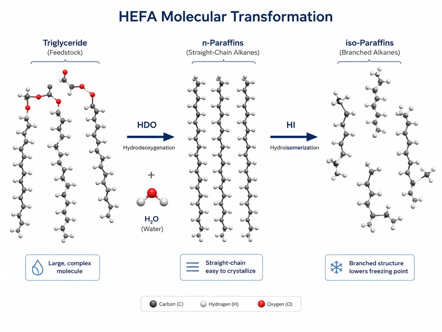
Triglycerides — the molecular form of fats and oils — are essentially three long fatty acid chains (typically C16–C18) esterified to a glycerol backbone, with six oxygen atoms embedded in the structure. To become a hydrocarbon fuel, every one of those oxygen atoms must be removed.
The HDO reactor does this work at high temperature and pressure — typically 280 to 340°C and 50 to 100 bar — in the presence of hydrogen and a sulfided bimetallic catalyst, most commonly nickel-molybdenum supported on alumina (NiMo/Al2O3). The reaction splits triglycerides into three free fatty acid chains and hydrogenates them, removing oxygen primarily as water (the HDO pathway) and to a lesser extent as CO and CO2 (the decarboxylation and decarbonylation pathways).
The choice between these competing pathways matters economically. HDO preserves the full carbon chain length (C18 → C18) but consumes more hydrogen. Decarboxylation uses less hydrogen but sacrifices one carbon atom per chain (C18 → C17), reducing overall carbon yield. The ratio of C17 to C18 n-paraffins in the reactor product is the field metric for HDO selectivity. Leading catalyst formulations — such as Topsoe’s Mo/Al2O3 system — can achieve up to 97% HDO pathway selectivity, maximizing the renewable carbon retained in the fuel product.
The HDO reactor effluent contains more than just n-paraffins. It carries water produced by the reaction (roughly 100–120 kg per metric ton of feedstock), along with ammonia from nitrogen-containing compounds and hydrogen sulfide from sulfur in the feed. If any of this carries over to the next reactor, the consequences are severe: water vapor and ammonia poison the noble metal catalysts in the hydroisomerization step. Even trace levels can slash isomerization activity within hours.
Hydroisomerization and Hydrocracking — Tailoring Molecules for the Cold Sky
The straight-chain n-paraffins emerging from HDO have one critical flaw: they freeze. A C16–C18 n-alkane solidifies at temperatures well above 0°C, while Jet A-1 must remain liquid down to −47°C at cruising altitude. The gap between what HDO produces and what an aircraft engine requires is bridged by the hydroisomerization (HI) reactor.
HI transforms straight-chain paraffins into branched iso-paraffins through a bifunctional catalyst mechanism. Metal sites (typically platinum or palladium) provide hydrogenation-dehydrogenation activity; acidic support sites catalyze skeletal rearrangement. The support material itself is critical — and this is where zeolites and molecular sieves enter the chemistry, not just the purification. SAPO-11 has a precisely defined pore structure of 0.39 nm × 0.63 nm, with elliptical 10-membered ring channels. This shape-selective framework favors the formation of mono-branched isomers with dramatically lower freezing points, while minimizing unwanted cracking to lighter products.
Simultaneously, controlled hydrocracking breaks longer chains (C18–C22) down into the jet fuel carbon range (C8–C16). The art of the HI step is balancing these two reactions: isomerize enough to meet the −47°C freezing point specification, but don’t over-crack — every carbon atom that ends up in naphtha or fuel gas is carbon that didn’t become jet fuel.
This is also where the single-stage versus two-stage configuration decision becomes material. In single-stage operation (“sour mode”), HDO effluent flows directly to the HI reactor without intermediate purification. The ammonia and hydrogen sulfide present suppress noble metal catalyst activity by 70 to 90%, limiting isomerization depth and SAF yield — typically below 15% of the total liquid product. In two-stage operation (“sweet mode”), the HDO effluent undergoes intermediate gas-liquid separation and purification before entering the HI reactor, which then operates free of NH3 and H2S. Isomerization activity increases 3- to 5-fold, and SAF yield jumps to 75–80% of the product slate.
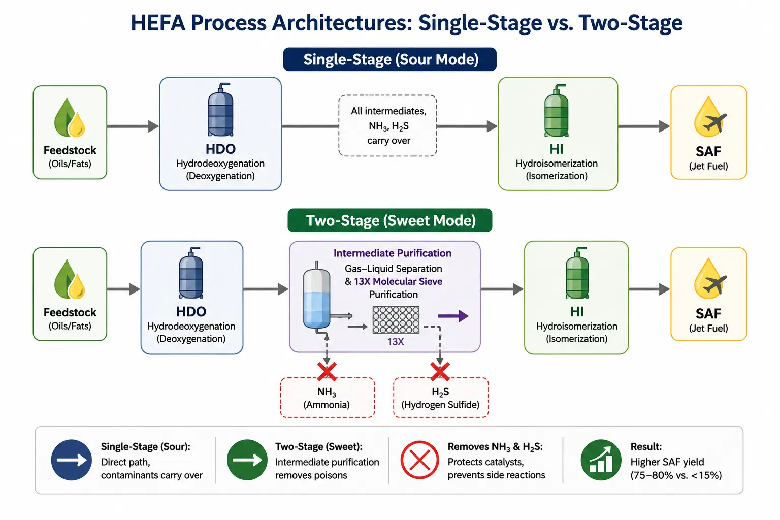
The commercial implication is stark: a plant that skips the intermediate purification layer — or specifies it inadequately — is not a SAF plant. It is a renewable diesel plant that makes a token amount of jet fuel.
Fractionation and Blending — The Final Cut
The combined reactor effluent is separated by distillation into four product fractions: fuel gas and LPG (C1–C4), naphtha (C5–C12), the SAF cut (C8–C16 synthetic paraffinic kerosene), and renewable diesel (C10–C22). In maximum-SAF mode, the jet fuel cut accounts for 75–80% of the total liquid product, with the balance split between diesel and naphtha.
The neat HEFA-SPK is then blended with conventional Jet A-1 at up to 50% by volume, the limit established by ASTM D7566. The constraint is aromatic content: HEFA-SPK is essentially 100% paraffinic, containing virtually no aromatics, while jet fuel specifications require a minimum of 8% aromatics to ensure elastomer seal swell in aircraft fuel systems. The 50% blend ceiling ensures sufficient aromatic carryover from the conventional jet fuel portion.
Additives — lubricity improvers, antioxidants, and in some cases static dissipaters — complete the formulation, and the finished fuel is redesignated as D1655 Jet A-1, indistinguishable in handling and performance from its fossil counterpart.
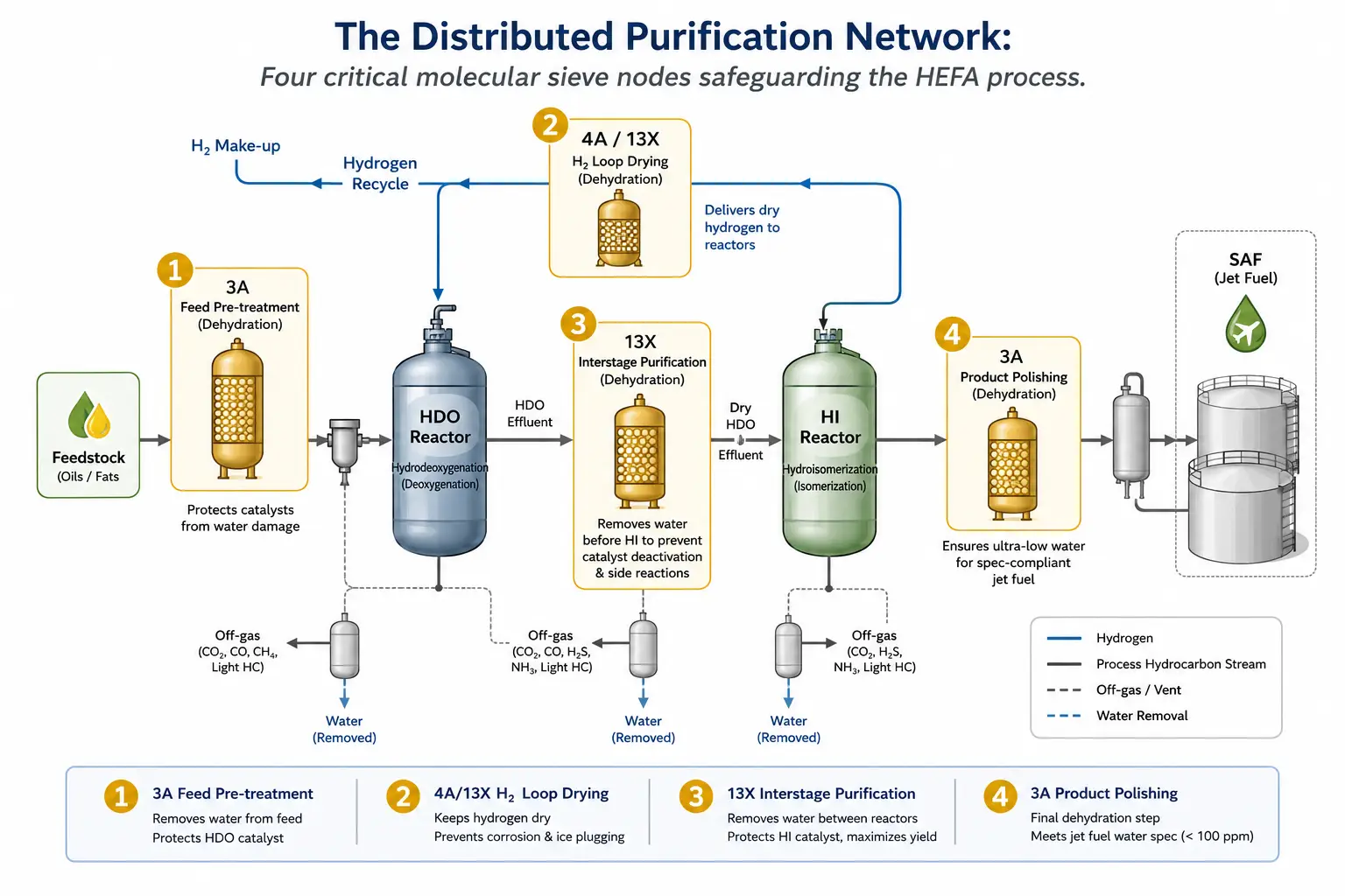
The Overlooked Purification Layer — Where Molecular Sieves Make or Break HEFA Performance
Public discussion of the HEFA process devotes roughly 95% of its attention to reactor chemistry and catalyst performance. But every industrial HEFA plant’s reliable operation depends on a “fifth step” that runs invisibly alongside the main process: a distributed network of molecular sieve purification units deployed at four strategic nodes. Omit this layer from your mental model of HEFA, and you are looking at a flow diagram of a chemistry experiment — not an operable production facility.
This section walks through each of those four purification nodes. For each, the core question is the same: what needs to be removed, what happens if it is not, and what type of molecular sieve is best suited to the task?
Feedstock Pretreatment — Guarding the Guard Bed
Before feedstock enters the HDO reactor, it passes through a pretreatment train designed to intercept contaminants that would otherwise irreversibly damage downstream catalysts. While guard-bed catalysts within the HDO reactor handle phosphorus and metals at the reaction level, a physical adsorption step upstream provides the last line of defense.
Used cooking oil and animal fats arrive with dissolved water (0.1–0.5 wt%), water-soluble salts, polar organic compounds, and trace metals. Water entering the HDO reactor reduces hydrogen partial pressure through dilution, promotes water-gas shift side reactions that consume valuable hydrogen, and accelerates hydrothermal catalyst sintering. Polar compounds and metal salts poison active sites on contact.
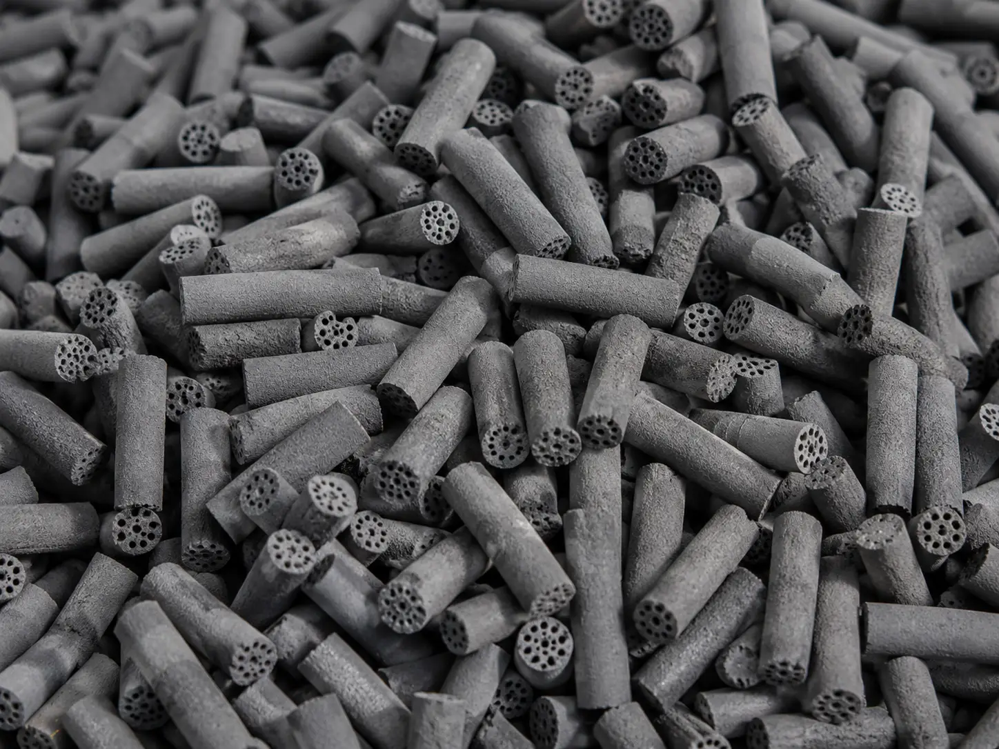
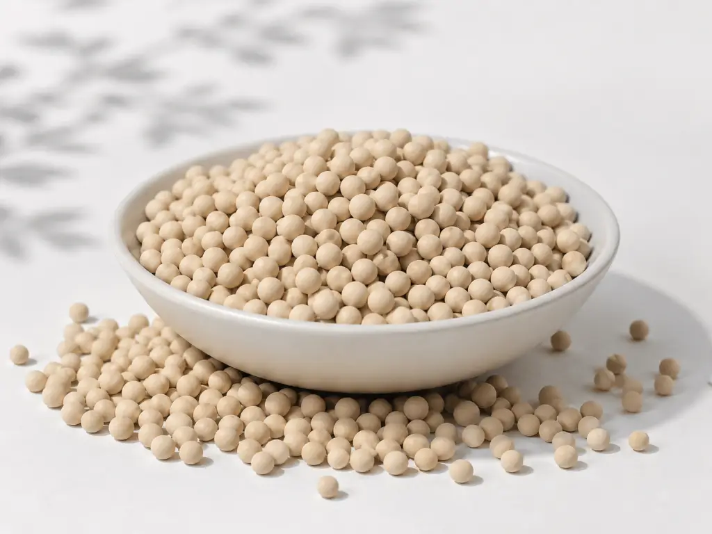
The solution is a pretreatment adsorption bed loaded with 3A molecular sieve and activated alumina, installed upstream of the feed heater. The 3A sieve’s pore opening — approximately 3 Å — is sized to admit water molecules (kinetic diameter ~2.65 Å) while excluding larger hydrocarbon molecules (4–10 Å). Water enters the pore and is adsorbed; larger organic molecules remain in the bulk liquid phase, preventing both pore blockage and the exothermic risk of co-adsorbing hydrocarbons. Activated alumina in the same bed captures polar compounds through its amphoteric surface chemistry.
The impact on catalyst life is measurable: adequate pretreatment adsorption can extend guard-bed catalyst replacement intervals by 30 to 50%, directly reducing both catalyst procurement costs and production downtime.
Hydrogen Recycle Gas Drying — Protecting the Noble Metal Catalyst
The HDO reaction generates roughly 100–120 kg of water per ton of feedstock processed. After the reactor effluent is cooled and separated, the hydrogen-rich gas stream — still saturated with water vapor at a dew point of 40 to 60°C — is recycled back to the reactor inlet. If that moisture is not removed, it accumulates in the loop, progressively diluting hydrogen partial pressure, reducing HDO reaction rate, and accelerating catalyst deactivation through hydrothermal sintering.
In a two-stage configuration, the consequences escalate further: moisture carried into the HI reactor poisons platinum- and palladium-based catalysts. Industry data indicates that sustained exposure to inlet water concentrations above 50 ppm can produce observable declines in isomerization activity. At higher moisture loads, SAF yield can drop from the design target of 75% to below 50% within days.
The standard solution is a hydrogen recycle dryer — a twin-bed thermal-swing adsorption unit filled with 4A or 13X molecular sieve, depending on the gas composition. A 4A molecular sieve (pore opening ~4 Å) selectively adsorbs water while excluding most hydrocarbons. Under typical operating conditions of 40°C and 30 bar, it achieves a dynamic water adsorption capacity of 20 to 22 wt%. The target outlet dew point is −60°C or lower, corresponding to a water content below 10 ppmv. When CO2 is present in significant quantities in the recycle gas, specialized adsorbent selection or a dedicated CO2 removal step may be required, as both 4A and 13X molecular sieves adsorb CO2, with 13X having higher co-adsorption capacity for CO2 alongside water.
The twin-bed configuration ensures uninterrupted operation: while one bed is in adsorption service (typically 8 to 24 hours depending on flow rate and moisture load), the other undergoes thermal regeneration at 200 to 300°C using a slipstream of dry product gas or nitrogen.
Intermediate Dehydration — The Sweet Mode Enabler
It is the intermediate purification step — the equipment between the HDO and HI reactors in a two-stage configuration — that most distinguishes a SAF-optimized HEFA plant from a renewable diesel facility.
In single-stage operation, the entire HDO effluent, including water, ammonia, and hydrogen sulfide, enters the HI reactor. Noble metal catalyst activity is suppressed by 70 to 90% under these conditions, and the plant produces predominantly diesel-range hydrocarbons with minimal jet-range product. In two-stage operation, the HDO effluent undergoes cooling, gas-liquid separation, acidic gas scrubbing (amine wash or water wash), and finally adsorption-based polishing through a molecular sieve bed.
The adsorption medium for this service is typically 13X molecular sieve, whose ~10 Å pore opening simultaneously adsorbs residual water, ammonia, and trace hydrogen sulfide. The target is to reduce ammonia concentration below 1 ppmv at the HI reactor inlet, at which level noble metal catalyst activity is fully expressed. Under these sweet-mode conditions, isomerization activity increases by a factor of 3 to 5, and SAF yield shifts from less than 15% to 75–80% of the total liquid product.
The intermediate purification section typically accounts for 5 to 8% of a two-stage HEFA plant’s total capital cost. What it buys is the difference between a diesel plant and a jet fuel plant.
Product Purification — The Final Polish
The last purification node sits at the boundary between production and storage. The distilled SAF fraction, even after passing through all upstream processing, can pick up dissolved moisture during tank storage — a consequence of diurnal temperature cycling that draws humid ambient air into tank headspace. Dissolved water, even at concentrations below 50 ppm, presents a risk at cruising altitude: as fuel temperature drops toward ambient (−50 to −60°C at 35,000 feet), dissolved water can precipitate as microscopic ice crystals that clog fuel filters and cause engine flameout.
A final product polishing step through a 3A molecular sieve dryer — operating at ambient temperature with a liquid hourly space velocity of 4 to 12 h−1 — reduces dissolved water content below 15 ppm, the practical upper limit for Jet A-1 to remain clear of free water across the full flight envelope.
Taken together, these four molecular sieve applications — 3A for feed pretreatment, 4A or 13X for hydrogen recycle drying, 13X for intermediate purification, and 3A for final product polishing — form a distributed purification system that spans the entire HEFA process from feed tank to product tank. They rarely appear in the same sentence as the reactors and catalysts that dominate industry discussion. But without them, not a single drop of SAF reaches an aircraft fuel nozzle.
HEFA Technology Providers and Process Configurations
For project developers and engineering teams evaluating HEFA technology options, the landscape of commercial licensors breaks down into several well-defined offerings. The table below summarizes the major players based on publicly available information; actual technology selection must account for site-specific feedstock characteristics, target product distribution, and integration with existing refinery infrastructure.
| Technology Licensor | Process Name | Configuration Options | Catalyst Highlights | Representative Projects | Max SAF Yield |
|---|---|---|---|---|---|
| Topsoe | HydroFlex | Single-stage / Two-stage | Mo/Al₂O₃ HDO catalyst; 97% HDO selectivity | Montana Renewables, Phillips 66 Rodeo | ~75–80% |
| Honeywell UOP | Ecofining | Single-stage / Two-stage | Proprietary catalysts; 50+ active licenses | Diamond Green Diesel, World Energy Paramount | ~75% |
| Axens | Vegan | Two-stage | First commercial reference plant operating 8+ years | Galp, Green Carbon Development | ~75% |
| Neste | NExBTL (proprietary) | Two-stage with counter-current HI | Catalyst supplied by Ketjen | Porvoo, Singapore, Martinez (Marathon JV) | ~75% |
| Sulzer Chemtech | BioFlux | Liquid-full single reactor | Licensed from Duke Technologies | Thailand, Malaysia, Uruguay projects | N/A (RD-focused) |
Selecting a technology licensor is an essential first step — but it is only the first step. Regardless of whose process package is chosen, every HEFA plant requires the same underlying purification infrastructure. The molecular sieve dehydration, intermediate purification, and product polishing units are not optional extras in any licensor’s design; they are prerequisite unit operations that must be specified, sized, and sourced.
Molecular sieve dehydration, intermediate purification, and product polishing units are not optional extras in any licensor’s design. They are prerequisite unit operations that must be specified regardless of whose process package is chosen.
From Process Design to Plant Performance — Why the Purification Layer Matters
The standard HEFA textbook draws three boxes: HDO, hydroisomerization, and fractionation. But every plant designer who has taken a unit from FEED study to commissioning knows there is a fourth function running through all three — the purification layer that makes the chemistry possible.
The economic logic is straightforward. Noble metal HI catalysts cost $500,000 to over $1 million per reactor charge. Unplanned catalyst replacement triggered by water or ammonia poisoning not only incurs the direct replacement cost but also shuts down production — and a large-scale SAF plant producing 2,000 to 3,000 barrels per day loses roughly $2 million in revenue for every day of unplanned downtime. The molecular sieve purification systems that protect those catalysts represent 3 to 5% of total plant investment but influence more than 70% of variable operating cost through their effect on catalyst life, product yield, and on-stream reliability.
As global SAF capacity scales from approximately 1.5 million tons per year today toward the 400-plus billion liters per year needed by 2050 — requiring an estimated 5,000 to 7,000 new production facilities, according to IEA Bioenergy analysis — the purification layer will evolve from a design footnote to a competitive differentiator. The first generation of HEFA plants treated molecular sieve selection as an afterthought, often accepting whatever adsorbent the EPC contractor specified by default. The next generation, facing tighter margins, more variable waste feedstocks, and higher regulatory pressure on yield efficiency, will treat adsorbent specification as a design optimization variable in its own right.
For engineers specifying new HEFA capacity today, the practical takeaway is clear: invest as much rigor in adsorbent selection as in catalyst selection. The molecular sieves drying your hydrogen recycle loop are not a commodity item. The right specification, backed by application-specific testing and a supplier with proven industrial gas purification expertise, can mean the difference between five years of stable isomerization catalyst performance and an unplanned shutdown in year one.
References
- ASTM International. “ASTM D7566 — Standard Specification for Aviation Turbine Fuel Containing Synthesized Hydrocarbons.” 2025. https://www.astm.org/d7566.html
- SkyNRG. “The Basics of SAF Technology — The HEFA Process.” https://skynrg.com/sustainable-aviation-fuel/technology-basics/
- Bergwerff, J. “SAF Production via the HEFA Route: Chemistry and Catalysis.” Decarbonisation Technology, May 2025. https://decarbonisationtechnology.com/article/329/saf-production-via-the-hefa-route-chemistry-and-catalysis
- Shiflett, W. “Renewables Part 2: A Focus on SAF.” Digital Refining, 2025. https://www.digitalrefining.com/article/1003245/renewables-part-2-a-focus-on-saf
- IEA Bioenergy Task 39. “Progress in Commercialization of Biojet / Sustainable Aviation Fuels (SAF).” 2024. https://task39.ieabioenergy.com/
- van Dyk, S. et al. “Potential Synergies of Drop-in Biofuel Production with Further Co-processing at Oil Refineries.” IEA Bioenergy, 2019. https://www.ieabioenergy.com/
- Goh, B.H.H. et al. “Recent Advancements in Catalytic Conversion Pathways for Synthetic Jet Fuel Produced from Bioresources.” Energy Conversion and Management, 2022. https://doi.org/10.1016/j.enconman.2021.114974
- CZapp. “The Pros and Cons of the HEFA Pathway for SAF.” https://www.czapp.com/analyst-insights/the-pros-and-cons-of-the-hefa-pathway-for-saf/
- Ketjen / Albemarle. “ReNewFine Catalyst Portfolio.” Referenced via Decarbonisation Technology, May 2025.
- Jalon Zeolite. “Industrial Molecular Sieve and Adsorbent Solutions.” https://www.jalonzeolite.com/products/
- Jalon Zeolite. “Case Studies.” https://www.jalonzeolite.com/case-studies/
- Jalon Zeolite. “Technical Capability.” https://www.jalonzeolite.com/capability/