Hydrocracking Catalysts Explained: How Zeolite Chemistry Drives Refinery Performance
How a Hydrocracking Catalyst Works — The Bifunctional Engine
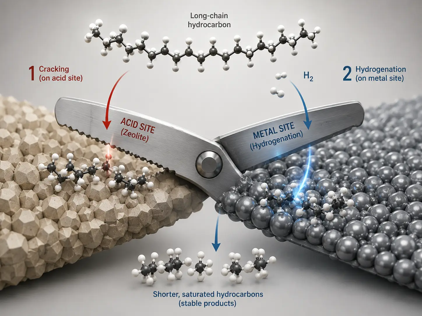
Every hydrocracking catalyst is, at its core, a two-part machine. The acid function — provided by a zeolite or amorphous silica-alumina support — cracks large hydrocarbon molecules into smaller ones and rearranges their skeletal structure through isomerization. The metal function — typically nickel, molybdenum, tungsten, platinum, or palladium impregnated onto the support — handles hydrogenation and dehydrogenation. These two functions must operate in precise balance. Too much acidity and the catalyst over-cracks, producing excessive light gas and coke. Too much metal activity and the catalyst over-hydrogenates, suppressing the cracking reactions needed for conversion.
In commercial operation, this balancing act runs at 10–20 MPa, 350–430°C, and hydrogen-to-oil ratios of 800–2,000 Nm³/m³. The acid site density in a typical hydrocracking catalyst falls between 0.2 and 0.5 mmol/g — a narrow window. Catalyst formulators hit that window by choosing specific zeolite types and dialing in their silicon-to-aluminum ratios. Get either wrong, and the unit lives with the consequences for the entire 2–5 year cycle.
Think of it as a pair of scissors. The acid sites are one blade, the metal sites the other. Neither blade cuts well on its own. Together, they slice carbon-carbon bonds with surgical precision — the zeolite determining where the cut happens, the metal providing the driving force. The rest of this article is about how to choose the right pair of blades for your feedstock and product goals.
Zeolite Types in Hydrocracking — The Molecular Architecture Behind Catalyst Performance
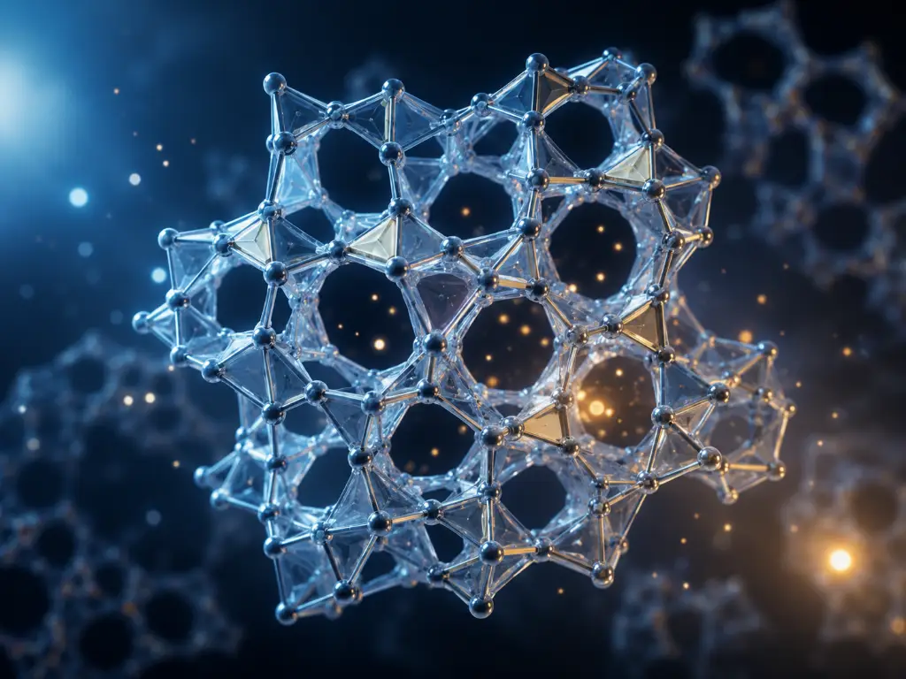
Before diving into individual zeolites, it helps to have a framework for evaluation. Three parameters define what any zeolite brings to a hydrocracking catalyst: pore size (which molecules can reach the active sites), the silicon-to-aluminum ratio or Si/Al (which controls acid strength and acid site density), and the Constraint Index or CI (which quantifies shape-selectivity — how strongly the pore structure discriminates between molecules of different shapes). Keep these three dimensions in mind as we examine each type.
USY and Dealuminated Y — The Industry Workhorse for Distillate Hydrocracking
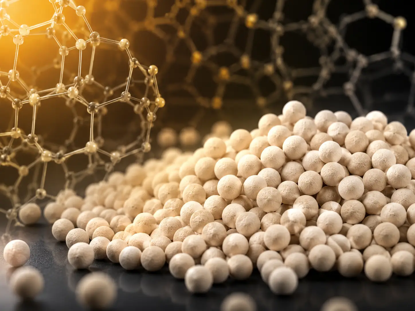
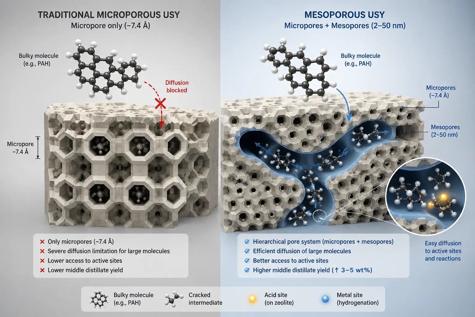
Ultra-stable Y zeolite, built on the FAU topology, dominates commercial hydrocracking. Its 12-member-ring pores measure roughly 7.4 Å in diameter and form a three-dimensional intersecting channel system — meaning reactant molecules always have multiple paths to reach an active site, much like a supermarket with three cross aisles instead of one. Over 70% of the world’s hydrocracking units run on Y-based catalysts.
The defining variable for USY is its framework Si/Al ratio. The starting material, NaY, has a Si/Al of around 3–6 and an acid site density too high for controlled hydrocracking — it would over-crack everything to gas. Through steam dealumination, framework aluminum is selectively removed, raising the Si/Al to anywhere from 20 to over 50 for the most heavily dealuminated grades. This matters because each aluminum atom creates one acid site. Higher Si/Al means fewer acid sites per unit mass — shifting the catalyst’s behavior from “indiscriminate cracker” to “selective splitter” by reducing secondary cracking, while the remaining sites, being more isolated, exhibit altered selectivity rather than uniformly stronger intrinsic acidity. For middle distillate maximization, Si/Al ratios above 20 are preferred because fewer acid sites reduce secondary cracking of diesel-range molecules.
Recent advances in mesoporous USY add a second level of porosity — 2–50 nm mesopores carved into the microporous crystal — that dramatically improves diffusion of bulky polynuclear aromatic molecules. In head-to-head comparisons, mesoporous USY delivers 3–5 wt% higher middle distillate yield, 2–3 wt% less gas make, and 5–8% lower hydrogen consumption compared to conventional USY under the same conditions (ScienceDirect review, 2020).
One critical caveat: rare-earth-exchanged Y zeolites (REY) — where RE³⁺ cations occupy sodalite cage sites to enhance framework stability — work well with noble metal catalysts (Pt, Pd) but can be actively detrimental when paired with non-noble metals (Ni-Mo, Ni-W). The rare earth cations interfere with the Ni-Mo-S or Ni-W-S active phase formation, reducing overall activity. If your feed requires base metal catalysts, avoid REY.
ZSM-5 and Medium-Pore Zeolites — Shape-Selective Cracking for Maximum Light Products
ZSM-5, built on the MFI topology, operates on an entirely different principle. Its 10-member-ring pores measure roughly 5.5 Å — narrow enough to admit normal paraffins and lightly branched iso-paraffins, but too tight for multi-branched isomers and polycyclic aromatics. This gives ZSM-5 a Constraint Index of 3–8, far higher than USY (CI < 1). In practice, it selectively cracks the low-octane normal paraffins in the gasoline boiling range while largely preserving multi-branched isomers and bulky aromatic molecules that cannot access its narrow pore channels.
ZSM-5 is almost never used alone in hydrocracking. Instead, it serves as an additive at 5–15 wt% blended into a USY-based main catalyst. At 10 wt% addition, it boosts light olefin (C₃–C₄) yield by roughly 3–5 percentage points — but each 5 wt% of ZSM-5 added also costs about 3–4 percentage points of diesel yield. The refiner’s calculus is straightforward: if light olefins command a premium over diesel in your market, ZSM-5 pays for itself.
Typical industrial ZSM-5 for hydrocracking has a Si/Al of 30 to over 300 — much higher than Y zeolites, producing far fewer acid sites. At moderate Si/Al (30–80), the remaining acid sites are relatively isolated and exhibit high turnover frequency for selective cracking; at very high Si/Al (>150), activity becomes diffusion-limited rather than acid-strength-limited. This is why ZSM-5 cracks selectively rather than indiscriminately: only molecules that can physically enter the pore and that encounter one of the sparse strong acid sites get converted.
Beta and Mordenite — Specialized Tools for Specific Feeds
Beta zeolite occupies a middle ground. Its 12-member-ring pores (roughly 6.6–7.0 Å) create a three-dimensional channel system slightly narrower than USY, with a Constraint Index of 0.6–2. This makes Beta inherently more paraffin-selective and less aggressive toward aromatics — an ideal profile for lubricant base oil production, where the goal is to crack wax (normal paraffins) while preserving the iso-paraffinic backbone that gives base oil its high viscosity index. Beta’s Si/Al range is extraordinarily wide — from 5 to near-infinity in pure-silica form — giving catalyst designers tremendous flexibility in tuning acidity for specific feedstocks.
Mordenite, by contrast, is a specialist for harsh service. Its 12-member-ring pores are arranged in a one-dimensional channel system — a single lane rather than USY’s highway network — making it prone to pore-mouth plugging by coke. But Mordenite compensates with exceptional acid resistance. In feeds containing 5,000+ ppm sulfur, Mordenite-based catalysts demonstrate substantially better structural stability than USY at equivalent Si/Al ratios. This makes it valuable in first-stage hydrocracking of heavy vacuum gas oil where the pretreat section may not achieve complete sulfur removal.
The Metal Side — Matching Hydrogenation Metals to Feed and Goals
If the zeolite determines what gets cracked and how, the metal component determines how well the intermediate olefins get saturated before they can recombine into coke. Four metal combinations dominate commercial practice:
| Metal System | Best Product Target | Feed Suitability | Key Limitation |
|---|---|---|---|
| Ni-Mo | Gasoline / naphtha maximization | VGO, sour feeds (high sulfur) | Moderate hydrogenation; can over-crack to light ends |
| Ni-W | Diesel / middle distillate maximization | VGO, high-nitrogen feeds | Strongest hydrogenation; lower cracking activity than Ni-Mo |
| Pt / Pd | High-octane gasoline, lube base oils | Pre-hydrotreated clean feeds only | Sulfur-sensitive: >10 ppm S causes rapid deactivation |
| Co-Mo | Hydrotreating / pretreatment | High-sulfur feeds | Lowest cracking activity; primarily a desulfurization catalyst |
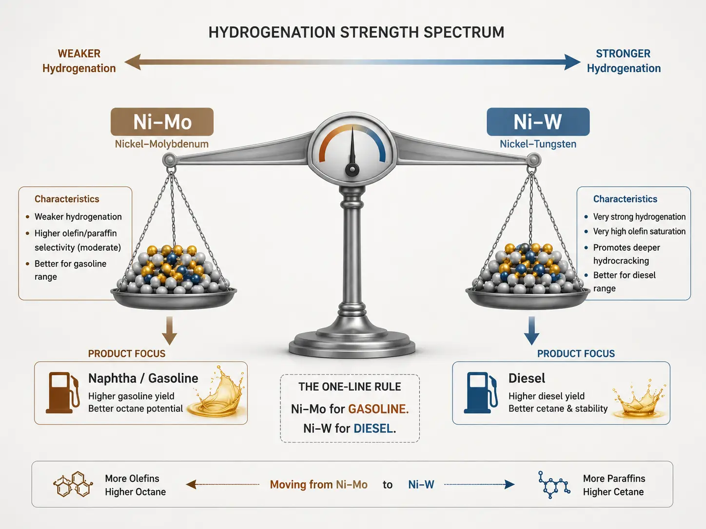
The industrial workhorses are Ni-Mo and Ni-W. A typical Ni-Mo catalyst carries 3–5 wt% NiO and 15–25 wt% MoO₃ on the support; a Ni-W formulation runs 4–6 wt% NiO and 20–28 wt% WO₃. The higher tungsten loading reflects tungsten’s heavier atomic weight and the fact that Ni-W catalysts require more metal to achieve the same active site density.
The product selectivity difference between these two systems is well established: Ni-W’s stronger hydrogenation function saturates aromatic rings more completely, preserving middle-distillate-range molecules from secondary cracking. Ni-Mo’s weaker hydrogenation leaves more olefinic intermediates, which re-crack to lighter products — desirable when naphtha is the target, undesirable when diesel is.
Noble metal catalysts (Pt, Pd) achieve extraordinarily high activity at loadings of just 0.3–1.0 wt% — roughly 20–50 times lower metal content than base metal systems. But this efficiency comes at a price: sulfur is lethal. Feed sulfur above 10 ppm permanently deactivates Pt sites, and even 50 ppm is catastrophic. Noble metal catalysts are therefore restricted to the second stage of two-stage hydrocracking units, where the first-stage pretreat catalyst has already stripped sulfur and nitrogen to trace levels.
Matching Catalyst to Feedstock and Product Goals — A Decision Framework
Selecting a hydrocracking catalyst is ultimately a three-input, one-output problem. The inputs are your feedstock properties (sulfur and nitrogen content, distillation range, aromaticity, metals), your target product slate (gasoline, jet fuel, diesel, or lube base oils), and your unit constraints (maximum hydrogen partial pressure, minimum space velocity, available quench capacity). The output is a recommended zeolite type, metal combination, and Si/Al range. Here is how the logic works for the three most common product targets.
Maximizing Gasoline and Light Olefins
This configuration favors higher acid site density and good secondary cracking activity. The standard recommendation is USY or REY with Si/Al in the 6–12 range paired with Ni-Mo, supplemented by 5–15 wt% ZSM-5 as an additive. Operating conditions lean toward the hotter end of the window (400–430°C) with hydrogen partial pressure maintained at a level sufficient to prevent rapid coking — typically 8–12 MPa total pressure — where the elevated temperature drives the secondary cracking that converts middle distillates into naphtha-range molecules.
Under these conditions, a well-optimized gasoline-mode hydrocracker can deliver 50–65 wt% naphtha yield and 10–18 wt% C₃–C₄ light olefins. The ZSM-5 additive is the key lever: every 5 wt% increase in ZSM-5 content adds roughly 1.5–2 percentage points of light olefin yield, at the cost of 3–4 percentage points of diesel. The refiner’s economic optimization is whether the olefin-to-diesel price spread justifies the ZSM-5 loading.
The acid site density target for gasoline mode is above 0.3 mmol/g — roughly double the target for distillate mode. This is achieved by keeping Si/Al low and, optionally, using REY whose rare earth cations stabilize the high-aluminum framework.
Maximizing Middle Distillates — Jet Fuel and Kerosene
This is where mesoporous USY earns its premium. The recommendation is high-Si/Al USY or dealuminated Y (Si/Al > 20) with Ni-W, processed at moderate temperature (380–410°C) and high hydrogen partial pressure (>12 MPa). Every 1 MPa increase in hydrogen partial pressure improves middle distillate selectivity by roughly 2–3 percentage points — the extra hydrogen saturates aromatics more completely, preventing them from condensing into coke precursors and freeing up active sites for continued operation.
The mesoporosity is not a minor tweak. Conventional USY forces bulky tri- and tetra-aromatic molecules to crack at or near the external crystal surface, where acid site accessibility is limited. Mesoporous USY provides internal highways — the large molecules enter the mesopores, undergo an initial ring-opening step, and the resulting smaller fragments then diffuse into the micropores for selective secondary cracking. The net result is a documented 3–5 wt% increase in jet fuel plus diesel yield versus a conventional USY catalyst processing the same VGO feed.
Typical yields for a well-run middle-distillate hydrocracker: 35–45 wt% jet fuel / kerosene, 20–30 wt% diesel, with total middle distillate in the 55–75 wt% range depending on feed quality and cut points.
Maximizing Diesel and Lubricant Base Oils
Diesel maximization pushes the same logic as middle distillates but further: Si/Al above 30, Ni-W metals, and temperatures kept in the 370–400°C range to suppress secondary cracking. The target diesel properties — cetane number above 55, cold filter plugging point below −10°C — are achieved through a combination of deep aromatic saturation (driven by Ni-W at high hydrogen pressure) and mild isomerization of normal paraffins (driven by the zeolite’s weak residual acidity).
Lubricant base oil production is a fundamentally different challenge. The goal is not to maximize cracking but to selectively remove molecules that hurt low-temperature performance (waxes — normal paraffins with high pour points) while preserving the iso-paraffinic structures that give base oil its high viscosity index. This requires Beta zeolite paired with a Pt or Pd noble metal catalyst, operating at 12–18 MPa hydrogen pressure. The catalyst’s job is to isomerize normal paraffins to branched isomers rather than crack them — a far more delicate operation than bulk hydrocracking, reflected in a catalyst cost 3–5 times higher per ton than conventional diesel hydrocracking catalysts.
In all three cases, the common thread is that zeolite parameters — Si/Al ratio, pore architecture, crystal size — are the hidden variables that ultimately determine whether a catalyst hits its yield targets. A refinery that specifies product goals without understanding the zeolite chemistry behind them is steering blind.
Catalyst Deactivation and Lifecycle — What Happens After Loading
A fresh hydrocracking catalyst does not stay fresh for long. The moment feed hits the bed, three deactivation mechanisms begin competing for control of the catalyst’s useful life.
Coke deposition is typically the largest contributor to activity loss in VGO hydrocracking, though its relative importance varies with feedstock quality and operating severity — metal deposition dominates in residuum-processing units, while coke governs fixed-bed VGO service. The first 48–72 hours on stream typically see the sharpest activity decline — initial coke laydown on the most active sites — after which the deactivation rate settles into a slower, quasi-linear regime. Catalyst manufacturers design for this: the “start-of-run” activity quoted in data sheets assumes this initial stabilization has already occurred.
Metal deposition from feedstock contaminants — primarily nickel, vanadium, and iron — is slower but irreversible. Unlike coke, which can be burned off during regeneration, contaminant metals accumulate permanently in the catalyst pores and on the external surface. A refinery processing high-metals vacuum gas oil may lose 10–15% of its catalyst’s effective pore volume to metal deposits over a single cycle.
Hydrothermal sintering — the gradual collapse of the zeolite framework under the combined assault of high temperature and steam — is the slowest but ultimately the most terminal mechanism. Every time the catalyst sees temperatures above 450°C in the presence of water vapor (which is always present from hydrogenation of oxygenates and from quench steam), a few more framework aluminum atoms detach, a few more acid sites are lost. This is cumulative and irreversible.
The standard countermeasure is regeneration: controlled burn-off of accumulated coke in an air or air-steam mixture at 450–520°C. The temperature window is narrow — below 450°C, soft coke burns incompletely; above 520°C, the zeolite framework itself begins to degrade. A well-executed regeneration recovers 90–95% of the catalyst’s original activity the first time, 80–90% the second, and 70–80% the third. Beyond three regenerations, the framework damage and metal accumulation typically make further cycles uneconomical. As Jeff Johns, a former Chevron Hydroprocessing Fellow with over 35 years in the field, puts it: “Never load the same catalyst more than twice without a robust re-evaluation process” (Becht Blog, 2023).
The end-of-life trigger varies by unit, but a common rule of thumb: when maintaining target conversion requires operating at the reactor’s maximum allowable temperature (typically 425–440°C), or when bed pressure drop exceeds design limits due to coke and fines accumulation, the catalyst is due for replacement.
How to Evaluate and Select a Catalyst Supplier
Choosing a hydrocracking catalyst is a multi-million-dollar decision whose consequences play out over a 2–5 year operating cycle. Yet according to a survey published in PTQ Magazine, over 50% of catalyst selections are based primarily on vendor forecasts — the riskiest possible approach (Digital Refining, 2019). A more rigorous evaluation framework includes five dimensions.
Pilot plant testing with your own feed. Jeff Johns’ first tenet of catalyst selection: “In God we trust, all others bring data.” Any credible catalyst supplier should be able to run your feedstock through their pilot plant or micro-reactor and provide side-by-side performance data against your incumbent catalyst. Without this, you are buying a forecast, not a product.
Yield structure verification. Product yields account for roughly 90% of the economic value of a catalyst decision. A new catalyst that costs 20% more but delivers 4 wt% additional middle distillate yield — as documented in a European refinery’s switch to a diesel-selective catalyst (Digital Refining, 2016) — can pay back its premium within months. The minimum economic hurdle: a 3:1 payout ratio — every dollar of additional catalyst cost must return at least three dollars in margin improvement.
Catalyst system integration. Pretreat and cracking catalysts must be selected as an integrated system, not as independent picks. The pretreat catalyst determines how clean the feed entering the cracking bed will be; the cracking catalyst’s performance depends entirely on that upstream cleaning. A world-class cracking catalyst paired with an undersized pretreat section is wasted capital.
Zeolite sourcing transparency. One question that rarely gets asked — but should — is: where does the catalyst manufacturer source its zeolites? Many catalyst companies buy zeolite powder from third-party producers, formulate it with binders, and impregnate metals. Others control the entire chain from zeolite synthesis through forming, metal impregnation, and final calcination. Companies with in-house manufacturing capability and certified quality management systems — for instance, operations holding ISO 9001, ISO 14001, ISO 45001, and ISO 50001 certifications alongside DUNS registration — offer a different risk profile than those relying on external zeolite supply chains. The difference shows up in batch-to-batch consistency over multi-year supply agreements, where even small variations in zeolite Si/Al or crystal size can shift product yields by a full percentage point.
Spent catalyst management. The catalyst decision does not end when the cycle ends. Does the supplier offer spent catalyst handling, metals reclamation, or regeneration services? These after-market capabilities affect the total cost of ownership across multiple cycles at least as much as the initial catalyst price.
The goal of structured supplier evaluation is not to find the cheapest catalyst. It is to find the catalyst whose yield structure, cycle life, and supply reliability deliver the lowest total cost per barrel of target product over the full operating horizon — a number that depends far more on zeolite chemistry and manufacturing quality than on the price per ton printed on the purchase order.
References
- Alasseel, A. et al. “Synthesis and performance evaluation of hydrocracking catalysts: A review.” Journal of Industrial and Engineering Chemistry, 2020. https://www.sciencedirect.com/science/article/abs/pii/S1226086X2030280X
- Johns, J. “Tenets of Catalyst Selection.” Becht Blog, February 2023. https://becht.com/becht-blog/entry/under-pressure-ii/
- “Refinery Catalyst Testing.” PTQ / Digital Refining, 2019. https://www.digitalrefining.com/article/1002336/refinery-catalyst-testing
- “Maximising the Diesel Yield from Hydrocracking.” Digital Refining, 2016. https://www.digitalrefining.com/article/1001340/maximising-the-diesel-yield-from-hydrocracking-ti
- JALON Zeolite — Quality Management. https://www.jalonzeolite.com/quality/
- JALON Zeolite — Manufacturing Capability. https://www.jalonzeolite.com/capability/
- JALON Zeolite — Home. https://www.jalonzeolite.com/
- JALON Zeolite — About. https://www.jalonzeolite.com/about/