Hydrocracking Technology and Process: How Modern Refineries Turn Heavy Oil into High-Value Fuels
What Is Hydrocracking and Where Does It Sit in the Refinery?
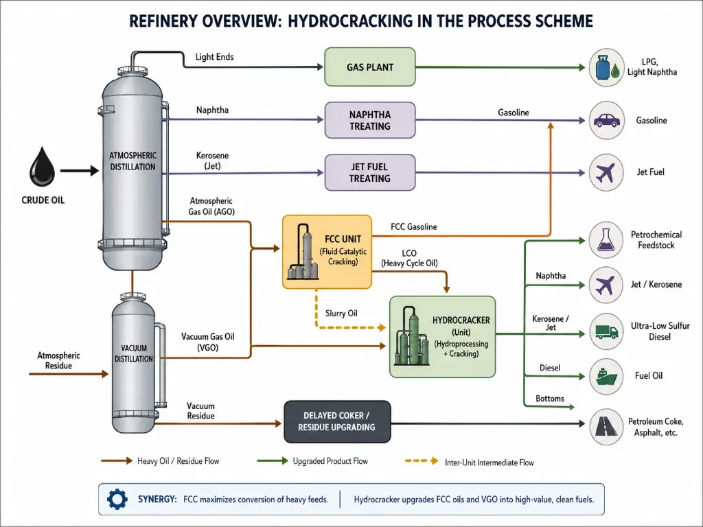
A refinery works like a sorting and upgrading factory. Crude oil enters at one end, and a spectrum of products — gasoline, diesel, jet fuel, petrochemical feedstocks — exits at the other. The atmospheric and vacuum distillation units handle the sorting: they separate crude into fractions by boiling point. But sorting alone leaves serious value on the table. The heavy fractions that emerge from the bottom of the distillation towers — gas oils and residual streams — are too large, too aromatic, and too contaminated to sell as premium products.
This is where hydrocracking comes in.
Hydrocracking is a catalytic hydrogenation process that cracks heavy hydrocarbon molecules into lighter, higher-value products. Unlike simple thermal cracking, it operates in a hydrogen-rich environment under high pressure, simultaneously breaking carbon-carbon bonds and saturating the fragments with hydrogen. The result is a product slate dominated by middle distillates — diesel, jet fuel, and heating oil — that are cleaner, more stable, and more valuable than the feedstock that entered the unit.
In the refinery flow scheme, the hydrocracker sits downstream of distillation and upstream of product blending. It complements the fluid catalytic cracker (FCC): the FCC converts gas oils into gasoline through a carbon-rejection mechanism, while the hydrocracker handles the more aromatic, refractory feedstocks that resist FCC cracking — including the light cycle oil (LCO) byproduct that the FCC itself produces. Together, these two conversion units form the backbone of a modern high-conversion refinery.
Why has hydrocracking become indispensable? Three forces converge. First, environmental regulations demand ultra-low-sulfur fuels — and hydrocracking’s hydrogen-rich environment strips sulfur and nitrogen down to single-digit ppm levels. Second, the global crude slate grows heavier, pushing more residual material into the refinery’s conversion units. Third, demand for middle distillates — particularly diesel in emerging economies and jet fuel for expanding air travel — continues to rise, and hydrocracking is the most efficient route to produce them.
So what actually enters a hydrocracker? That question turns out to be more nuanced than it sounds.
Feedstock: What Goes Into a Hydrocracker?
The hydrocracker’s defining strength is its feedstock flexibility — but that flexibility comes with engineering consequences. Different feeds demand different process configurations, different catalysts, and different operating strategies. Understanding the feedstock landscape is essential before diving into the process itself.
The lightest common hydrocracker feed is straight-run light gas oil (LGO), boiling in the range of approximately 200–370 °C, with vacuum gas oil (VGO) representing the majority of commercial feeds. These streams are relatively clean — low in sulfur and nitrogen — and can be processed in a single-stage configuration with modest hydrogen consumption. At the opposite extreme, vacuum residue — the material left behind after vacuum distillation, boiling above 565°C — contains high concentrations of metals (nickel, vanadium), asphaltenes, and polycyclic aromatics that would rapidly deactivate a conventional fixed-bed catalyst. Processing residue requires ebullated-bed or slurry-bed reactor technology, where catalyst can be continuously added and withdrawn.
Most commercial hydrocrackers operate somewhere in between. The workhorse feed is vacuum gas oil (VGO), typically boiling from 350 to 565°C. Depending on the crude source, VGO can contain anywhere from 0.5 to 4 wt% sulfur and 500 to 3,000 ppm nitrogen — and nitrogen is the stealthier problem. Organic nitrogen compounds, even at trace levels, are potent poisons for the acidic sites on the hydrocracking catalyst. That is why every hydrocracker, regardless of configuration, begins with a pretreatment step.
| Feedstock Type | Typical Source | Boiling Range | Key Challenge | Suitable Process |
|---|---|---|---|---|
| Straight-Run LGO/VGO | Atmospheric/Vacuum Distillation | 350–565°C | S, N content varies by crude | Single-Stage or Two-Stage |
| Light Cycle Oil (LCO) | FCC Byproduct | 220–350°C | High aromatics (60–80%), difficult to crack | Two-Stage with high-pressure H₂ |
| Coker Gas Oil | Delayed Coking | 350–520°C | High S, N, and olefins; unstable | Two-Stage with pretreatment |
| Atmospheric Residue | Atmospheric Distillation Bottoms | 565°C+ | Metals, asphaltenes, high viscosity | Ebullated Bed / Slurry |
| Vacuum Residue | Vacuum Distillation Bottoms | 565°C+ | Extreme metals + asphaltenes | Ebullated Bed / Slurry only |
The pretreatment requirement creates a natural segue into the process itself. Every hydrocracker, from the simplest single-stage unit to the most complex resid-upgrading facility, follows a logical sequence of steps that converts contaminated heavy feed into clean, specification-grade products.
The Hydrocracking Process: A Step-by-Step Breakdown
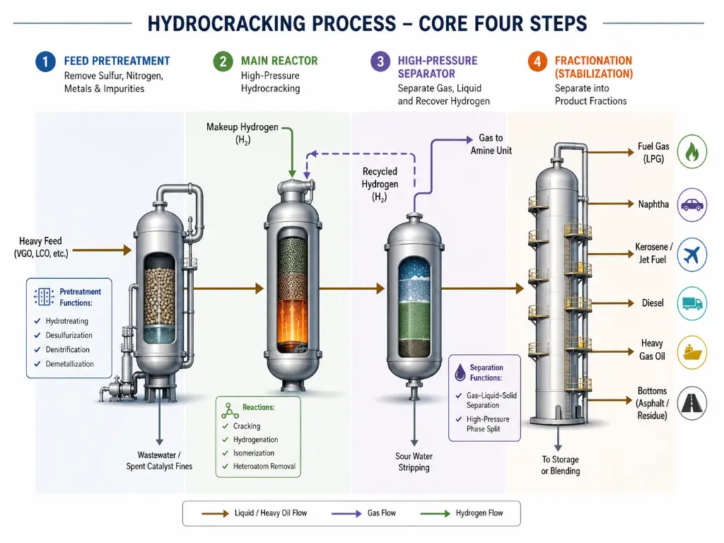
Hydrocracking is not a single reaction in a single vessel — it is a carefully choreographed sequence of four engineering stages: pretreatment, reaction, separation, and fractionation. Each stage involves critical operating decisions that cascade downstream, affecting product quality, catalyst life, and unit profitability.
Feed Pretreatment: Cleaning Up Before the Main Event
Think of pretreatment as the security screening and decontamination checkpoint before the main reactor. If sulfur, nitrogen, and metals reach the hydrocracking catalyst unchecked, they poison active sites, block pore channels, and shorten catalyst life from years to months.
The pretreatment reactor operates under conditions similar to the cracking reactor: temperatures of 300–400°C and hydrogen pressures of 50–150 bar. Inside, a CoMo (cobalt-molybdenum) or NiMo (nickel-molybdenum) catalyst drives two critical reactions. Hydrodesulfurization (HDS) converts organic sulfur compounds into hydrogen sulfide (H₂S), while hydrodenitrogenation (HDN) converts organic nitrogen compounds into ammonia (NH₃). The target leaving the pretreatment section is stringent: sulfur below 50 ppm and nitrogen below 10 ppm — with two-stage units often demanding nitrogen below 5 ppm to protect the second-stage noble-metal catalyst. Nitrogen must be driven especially low because organic nitrogen species neutralize the Brønsted acid sites that drive the cracking reactions downstream (Topsoe, 2004).
The Reaction Section: Where Cracking Happens
The pretreated feedstock, now cleaned of most heteroatom contaminants, mixes with heated, compressed hydrogen and enters the hydrocracking reactor — the heart of the unit. This is typically a fixed-bed, downflow (trickle-flow) reactor containing multiple catalyst beds separated by quench zones for temperature control.
What happens inside the catalyst particle is the defining chemistry of hydrocracking: the bifunctional mechanism. Each catalyst particle contains two distinct types of active sites in nanoscale proximity. Metal sites — typically sulfided nickel-molybdenum or nickel-tungsten in most reactors, with platinum or palladium reserved for second-stage units operating in a sulfur-free environment — perform hydrogenation and dehydrogenation. They saturate aromatic rings with hydrogen and, crucially, generate reactive olefin intermediates by removing hydrogen from saturated hydrocarbons. Acid sites — located on the zeolite or amorphous silica-alumina support — perform the cracking itself via β-scission, breaking carbon-carbon bonds in the olefin intermediates to produce smaller molecules.
This dual-site choreography is what makes hydrocracking selective rather than indiscriminate. The metal site activates the molecule; the acid site cuts it at a specific position. The two must be physically adjacent at the nanometer scale — a molecule desorbed from a metal site must encounter an acid site before it can re-saturate, or the opportunity to crack is lost.
Operating conditions reflect this delicate balance. Reactor temperatures span 300–450°C, with the exact setpoint determined by the feed reactivity and the target conversion level. Pressures range from 80 to 200 bar — higher pressures suppress coke formation by maintaining a high hydrogen partial pressure, but increase compression costs significantly. The liquid hourly space velocity (LHSV), typically 0.5–2.0 h⁻¹, controls residence time: lower LHSV means deeper cracking but lower throughput. The hydrogen-to-oil ratio, typically 1,000–2,000 Nm³ of hydrogen per cubic meter of feed, ensures adequate hydrogen availability at the catalyst surface and helps dissipate the exothermic heat of reaction (ScienceDirect, 2024).
Because cracking is strongly exothermic, temperature control is the reactor’s central safety challenge. Each catalyst bed raises the process stream temperature by 10–30°C. Between beds, cold hydrogen is injected as quench — a simple but tightly tuned control strategy. If a bed temperature runs away, the reaction rate accelerates exponentially, producing more heat, which further accelerates the reaction — a positive feedback loop that can lead to catalyst sintering or, in extreme cases, reactor wall failure.
Hydrogen Management: The Invisible Backbone
Hydrogen is the hydrocracker’s largest variable operating cost, and managing it well matters as much as managing the catalyst. A typical full-conversion hydrocracker consumes 250–350 Nm³ of hydrogen per ton of feedstock — making it the single largest hydrogen consumer in the refinery.
Hydrogen serves three roles simultaneously: it is a reactant (saturating cracked fragments and removing heteroatoms), a heat-transfer medium (carrying reaction heat away from the catalyst surface), and a catalyst protectant (suppressing coke formation by capping reactive coke precursors). The hydrogen that exits the reactor is not discarded — it passes through a high-pressure separator, where it is recovered, scrubbed of H₂S and NH₃, and recycled back to the reactor inlet. Fresh make-up hydrogen compensates for chemical consumption and purge losses. Maintaining recycle gas purity above 90% hydrogen is essential: accumulation of light hydrocarbons (methane, ethane) in the recycle loop depresses the hydrogen partial pressure, reducing catalyst activity and accelerating deactivation.
Separation and Fractionation: Sorting the Products
The reactor effluent is a complex mixture: unreacted hydrogen, light hydrocarbon gases (C₁–C₄), naphtha-range liquids, middle distillates, and unconverted oil. Sorting this mixture into specification-grade products requires two sequential separation steps.
First, the high-pressure separator flashes off the hydrogen-rich gas stream for recycle. The liquid phase, now at lower pressure, enters a fractionation column where products are drawn off according to boiling range: LPG (below 20°C), light naphtha (20–80°C), heavy naphtha (80–180°C), kerosene/jet fuel (180–270°C), diesel (270–370°C), and unconverted oil (370°C+). In a two-stage configuration, the unconverted oil is routed to a dedicated second-stage reactor for further cracking. In a single-stage unit, a portion may be recycled to the reactor inlet to boost overall conversion from a per-pass level of 40–60% to a total of 70–80%.
Process Control and Safety: Keeping It Stable
Operating a hydrocracker means managing a system under extreme conditions — 200 bar of hydrogen pressure at 400°C — where the margin between efficient operation and catastrophic failure can be narrow. Every commercial hydrocracker is equipped with an automatic emergency depressuring system. In the event of a temperature excursion or loss of containment, the system vents reactor contents to the flare within 15–20 minutes, dropping system pressure from over 200 bar to approximately 7 gauge (barg) — fast enough to quench the reaction before structural damage occurs.
Routine temperature control relies on the interbed quench hydrogen system. The target is to keep the temperature rise across each catalyst bed below about 20°C, ensuring stable operation without approaching the metallurgical limits of the reactor vessel. Operators monitor bed temperature profiles continuously; a hot spot developing in one bed can signal channeling, catalyst fouling, or uneven flow distribution — all of which require investigation before they escalate.
Single-Stage vs. Two-Stage: Choosing the Right Configuration
Once the basic process flow is understood, the next question is: how many reaction stages does the application require? The choice between single-stage and two-stage hydrocracking is not a matter of “which is better” — it is a matter of matching the configuration to the feedstock quality, the target conversion level, and the desired product slate.
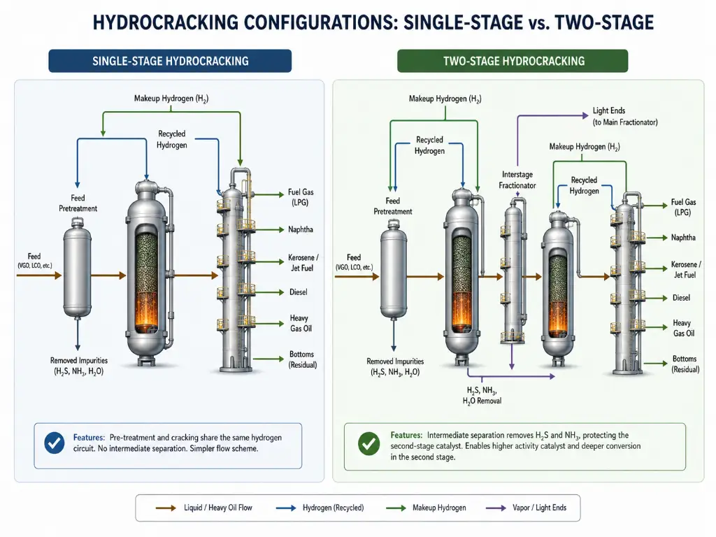
Single-Stage Hydrocracking: Simplicity for Light Feeds
In a single-stage configuration, the pretreatment reactor and the cracking reactor share a common hydrogen loop, with no intermediate product separation. The entire feed passes through both reactors in series, and the combined effluent proceeds directly to the separation section.
This simplicity translates to lower capital cost, smaller plot space, and simpler operation — making it the preferred choice for processing relatively light, low-contaminant feeds such as straight-run VGO from low-sulfur crudes. The trade-off is limited conversion: in once-through mode, typical per-pass conversion is 40–60%. Higher conversion can be achieved by recycling a portion of the unconverted oil back to the reactor inlet, pushing overall conversion to 70–80%, but the recycle stream carries unconverted polycyclic aromatics that accumulate in the loop and eventually force a purge.
The single-stage catalyst system must function in the presence of the H₂S and NH₃ generated during pretreatment. These gases partially inhibit the acidic cracking sites, which limits the per-pass conversion achievable — but also suppresses over-cracking to gas and coke, providing a natural selectivity toward middle distillates.
Two-Stage Hydrocracking: Maximum Flexibility for Challenging Feeds
The two-stage configuration adds a critical step between stages: product separation. After the first stage completes pretreatment and initial cracking, the effluent is fractionated. Light products (naphtha, kerosene, diesel) are drawn off as finished streams. The unconverted oil — now stripped of H₂S and NH₃ — enters a dedicated second-stage reactor operating in a clean hydrogen environment.
This intermediate separation is the key to the two-stage advantage. Freed from the H₂S and NH₃ that inhibit the first-stage catalyst, the second-stage reactor can employ more active catalysts — including noble metals like platinum and palladium on highly acidic zeolite supports — that would be rapidly poisoned in the first-stage environment. The result is deeper cracking per pass, higher overall conversion (90–99%), and the ability to shift the product slate toward diesel, jet fuel, or naphtha by adjusting second-stage operating conditions.
The cost, of course, is higher. Two-stage units require a second reactor, a second hydrogen loop (or a more complex shared loop), an interstage fractionator, and more catalyst inventory. For a refinery processing light, clean VGO into diesel, a single-stage unit may be entirely sufficient. For a refinery cracking LCO from the FCC, or processing high-nitrogen coker gas oil, or maximizing jet fuel production for a growing aviation market — the two-stage configuration earns its premium.
Operating Conditions and Reactor Technology
Understanding hydrocracking means understanding the tension between competing objectives: conversion depth versus product selectivity, catalyst activity versus catalyst longevity, product value versus operating cost. The operating parameters that balance these tensions, and the reactor hardware that contains them, are where process engineering meets physical reality.
| Operating Parameter | Typical Range | Engineering Logic |
|---|---|---|
| Reactor Temperature | 300–450°C | Lower bound set by catalyst light-off temperature; upper bound limited by excessive cracking to gas and rapid coke formation |
| Reactor Pressure | 80–200 bar | Higher pressure = higher hydrogen partial pressure = suppressed coke formation + longer catalyst life, but higher compression cost and thicker reactor walls |
| LHSV (Liquid Hourly Space Velocity) | 0.5–2.0 h⁻¹ | Inverse of residence time; lower LHSV = deeper cracking per pass but lower unit throughput |
| Hydrogen-to-Oil Ratio | 1,000–2,000 Nm³/m³ | Ensures catalyst surface hydrogen coverage, carries away reaction heat; too low = coke formation, too high = excessive recycle compressor load |
These parameters do not operate independently. Raising temperature increases conversion but also increases the rate of catalyst deactivation by coke. Increasing pressure suppresses coke but demands more expensive metallurgy and higher hydrogen compression costs. The art of hydrocracker operation lies in finding the sweet spot — and adjusting it as the catalyst ages and activity declines over its 3–5 year cycle.
The reactor hardware itself varies dramatically with feedstock severity, as captured in the comparison below (Penn State FSC 432, Penn State University):
| Bed Type | Catalyst Particle Size | Suitable Feedstock | Key Advantage | Key Limitation |
|---|---|---|---|---|
| Fixed Bed | 1.5–3 mm | VGO, LCO, Coker Gas Oil | Simple operation, lowest CAPEX, mature technology | Cannot handle feeds with metals or asphaltenes — these plug the bed |
| Ebullated Bed | 0.8–3 mm | Atmospheric Residue, Vacuum Residue | Catalyst can be added/withdrawn online; handles moderate metals | Higher CAPEX and OPEX; more complex operation |
| Slurry / Expanded Bed | ~0.002 mm (dispersed) | Ultra-Heavy Vacuum Residue | Extreme conversion (95%+); handles worst feeds | Catalyst is single-use (consumed); highest operating cost |
For the vast majority of commercial hydrocrackers processing VGO-range feeds, the fixed-bed configuration — robust, well-understood, and cost-effective — remains the standard. Ebullated-bed and slurry technologies are reserved for residue upgrading, where their higher cost is justified by the even higher cost of the alternative: leaving the bottom of the barrel unprocessed.
Operating parameters define the process window — but the molecular sieve inside the catalyst determines what that window actually produces. Custom zeolite formulation is the difference between hitting your product slate and living with compromises.
Explore Molecular Sieve SolutionsThe Zeolite Engine: How Molecular Sieves Drive Selective Cracking
If the reactor is the hydrocracker’s heart and hydrogen is its lifeblood, the zeolite inside the catalyst is its brain — the component that decides which molecules get cracked, how deeply, and into what products. This is the dimension of hydrocracking that most general-interest articles skip, yet it is where the deepest engineering leverage resides.
Pore Architecture: The Molecular Gatekeeper
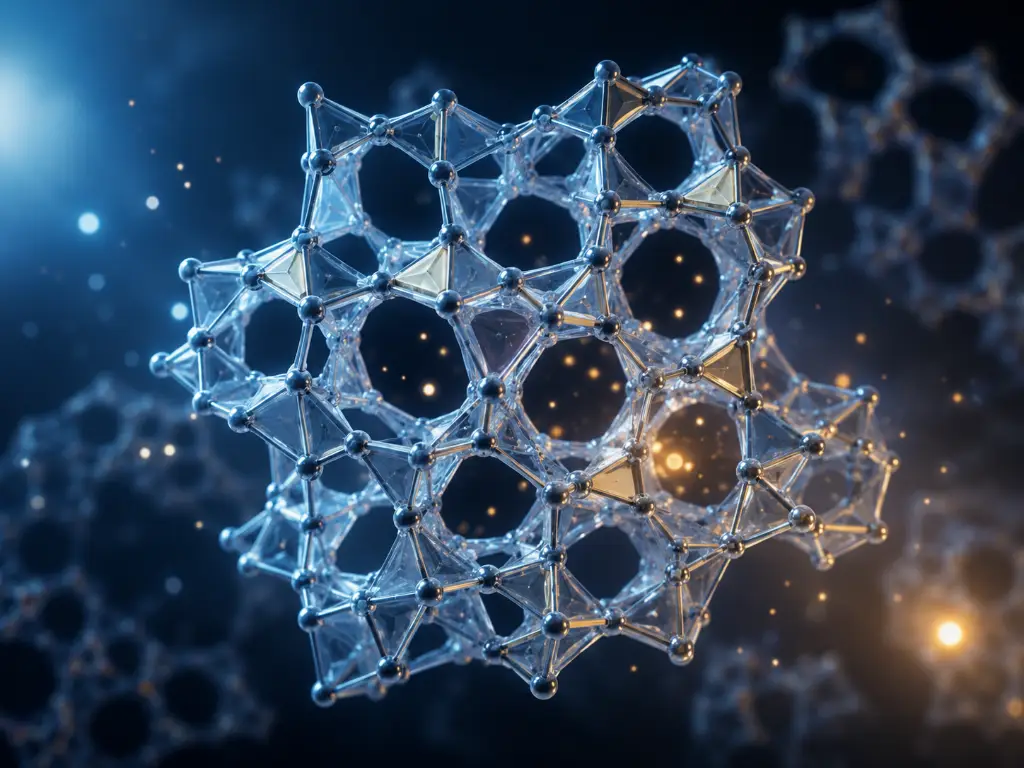
Zeolites are crystalline aluminosilicates with a defining feature: a three-dimensional framework pierced by pores of precisely uniform size. In hydrocracking, the dominant zeolite is ultrastable Y (USY), which belongs to the FAU topology family. Its structure contains 12-membered ring pore openings approximately 0.74 nm in diameter, leading into internal supercages roughly 1.2 nm across (MDPI Catalysts, 2025).
These dimensions are not arbitrary — they are matched to the molecular dimensions of the feedstock components the refiner wants to crack. Normal paraffins, with a kinetic diameter of about 0.49 nm, enter the pores freely and are rapidly cracked. Isoparaffins, at roughly 0.56 nm, enter more slowly. Single-ring aromatics (0.6–0.7 nm) can enter if they first undergo hydrogenation on a nearby metal site, which reduces their kinetic diameter. Larger multi-ring aromatics — particularly the three- and four-ring species prevalent in heavy cracked stocks and residue — approach or exceed 1 nm and are physically excluded from the FAU pore system, while the two-ring aromatics dominant in LCO (0.7–0.9 nm) enter only slowly and require prior hydrogenation. They must either be pre-cracked on external surface acid sites or processed through a mesoporous network deliberately introduced into the zeolite crystal.
This is shape selectivity — the physical basis of the “molecular sieve” name — and it is the fundamental reason zeolite-based catalysts outperform amorphous silica-alumina catalysts for selective hydrocracking. An amorphous catalyst presents acid sites to every molecule in the feed indiscriminately. A zeolite catalyst filters first, then cracks — preferentially upgrading the molecules that fit through its pores.
Acid Site Engineering: Controlling Cracking Depth
If the pore structure decides who gets in, the acid sites inside decide what happens next. Each aluminum atom substituted for silicon in the zeolite framework creates a net negative charge, balanced by a proton (H⁺). These protons are Brønsted acid sites — the catalytic centers where carbon-carbon bond cleavage occurs.
The density and strength of these acid sites are governed primarily by the framework silica-to-alumina ratio (SAR). A low SAR (e.g., 3–5) means more aluminum, more acid sites, and higher cracking activity — but also lower hydrothermal stability, because aluminum-rich frameworks are more vulnerable to steam-induced dealumination at high temperature. A high SAR (20–80, achieved through post-synthesis steam dealumination to produce USY) means fewer but stronger, more isolated acid sites — and dramatically better stability under hydrocracking conditions.
This SAR tuning is the refiner’s primary lever for product selectivity. A low-SAR catalyst with a high density of acid sites tends to over-crack — cutting molecules multiple times and producing more gas and light naphtha. A high-SAR USY catalyst, with its sparse but strong acid sites, tends to cut each molecule only once or twice — maximizing the yield of middle distillates. The same Y-type zeolite framework, at different SAR values, can shift the product slate from “maximum naphtha” to “maximum diesel” — all without changing the reactor hardware.
From Zeolite Powder to Industrial Catalyst: The Manufacturing Connection
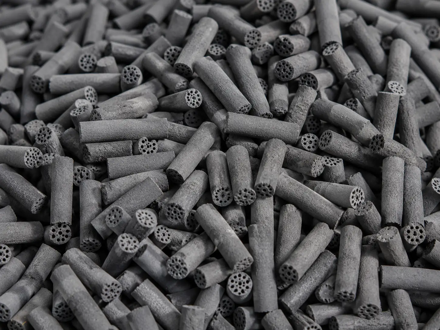
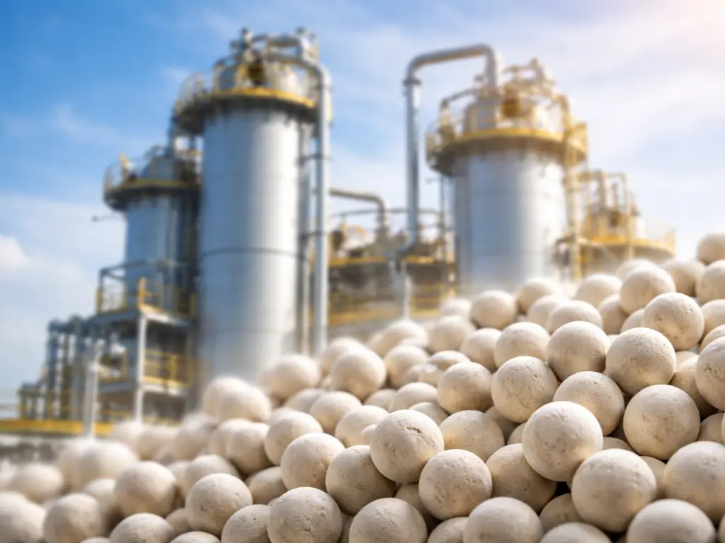
The journey from laboratory zeolite crystals to a commercial hydrocracking catalyst that can survive 200 bar and 400°C for 3–5 years is itself a significant industrial challenge. Zeolite powder — with its micron-scale crystals and negligible mechanical strength — must be formulated into millimeter-scale extrudates or spheres with the crush strength to resist bed compaction, the pore structure to facilitate molecular diffusion, and the attrition resistance to minimize dusting that would increase reactor pressure drop.
This formulation process — mixing zeolite powder with binder materials (alumina, clay), kneading, extruding, drying, and calcining — is where much of the catalyst manufacturer’s intellectual property resides. The binder is not inert filler; it contributes mesoporosity that improves diffusion of larger molecules, and its interaction with the zeolite can modify acid site accessibility. The target specifications are tightly controlled: crush strength typically above 10 N/mm (side crushing), attrition loss below 0.5 wt%, and a pore volume distribution balanced between micropores (in the zeolite) and mesopores (in the binder).
Different refining applications demand different zeolite configurations. A refiner cracking light VGO into maximum diesel needs a high-SAR USY with minimal acid site density and a formulation optimized for diffusion-limited operation. A refiner processing LCO into naphtha for a downstream catalytic reformer needs a lower-SAR zeolite with higher acidity, possibly incorporating a secondary zeolite like ZSM-5 (MFI topology) whose narrower 10-membered ring channels (0.51–0.56 nm) provide additional shape-selective cracking of straight-chain paraffins.
This is where the molecular sieve manufacturer’s technical depth directly impacts refinery economics. The ability to tailor crystal type (FAU, BEA, MFI, CHA), silica-to-alumina ratio, cation exchange (rare earth for stability, or specific metals for catalytic function), crystal size (D₅₀ from 0.5 to 10 μm), and forming parameters — and to deliver this customization with batch-to-batch consistency under ISO-certified quality systems — determines whether a refiner gets the product slate and catalyst life they designed for, or lives with compromises. Companies with deep in-house zeolite synthesis and formulation expertise make this critical material interface an optimization opportunity rather than a procurement constraint. JALON Zeolite — a publicly listed manufacturer with over 28 years of molecular sieve R&D, six provincial research platforms, five joint university laboratories, and complete customization capability across crystal types, SAR ranges, and cation specifications — is one such supplier. Technical teams evaluating molecular sieve options for hydrocracking or related refining applications can explore JALON’s product portfolio at jalonzeolite.com.
Product Yields, Flexibility, and Refinery Integration
The hydrocracker’s output is not a single product — it is a flexible slate that can be tuned to market demand. A representative product distribution for a VGO-fed two-stage hydrocracker illustrates the range:
| Product Fraction | Typical Yield (wt%) | Primary Use |
|---|---|---|
| LPG (C₃–C₄) | 5–10% | Cooking fuel, petrochemical feedstock |
| Light Naphtha (C₅–80°C) | 10–15% | Gasoline blendstock, ethylene cracker feed |
| Heavy Naphtha (80–180°C) | 25–35% | Catalytic reformer feed (BTX aromatics or high-octane gasoline) |
| Kerosene / Jet Fuel (180–270°C) | 15–25% | Jet A-1 aviation turbine fuel |
| Diesel (270–370°C) | 20–30% | Ultra-low-sulfur diesel (ULSD) blendstock |
| Unconverted Oil (370°C+) | 5–20% | FCC feed, fuel oil blendstock, or recycle to extinction |
The flexibility to shift between these yields is the hydrocracker’s strategic value. Raising the reactor temperature by 10°C typically increases conversion by 5–8 percentage points, pushing the product distribution toward lighter fractions. Switching between “maximum diesel,” “maximum jet,” and “maximum naphtha” modes is accomplished through adjustments to reactor temperature, LHSV, and — in two-stage units — second-stage catalyst selection and operating severity.
This product flexibility is what makes the hydrocracker indispensable in a modern refinery. When diesel margins are strong (as they have been in emerging markets with expanding trucking and construction sectors), the unit maximizes middle distillate yield. When gasoline or aromatics demand rises, the unit shifts toward heavy naphtha production for the catalytic reformer. When jet fuel consumption surges — driven by expanding air travel in Asia and the Middle East — the kerosene cut is maximized. The hydrocracker is the refinery’s Swiss Army knife.
And it does this while producing fuels that meet the most stringent environmental specifications. The hydrogen-rich environment saturates olefins and aromatics, producing diesel with cetane numbers above 50 and jet fuel with aromatics content below 25 vol% — both comfortably within international specifications (U.S. Energy Information Administration, 2013). The deep desulfurization inherent to the process means the diesel product can meet ultra-low-sulfur (≤10 ppm) specifications without a separate polishing hydrotreater.
In the broader refinery context, the hydrocracker and the FCC function as complementary conversion engines. The FCC produces primarily gasoline from VGO-range feed, rejecting carbon as coke on the catalyst. The hydrocracker produces primarily middle distillates from the FCC’s aromatic LCO byproduct and from heavier, more refractory gas oils — adding hydrogen rather than rejecting carbon. A refinery equipped with both units can process a wide range of crude slates, adjust product distribution to market conditions, and achieve overall conversion levels that neither unit could deliver alone.
Specify Your Hydrocracking Molecular Sieve Requirements
Custom crystal type, silica-to-alumina ratio, cation exchange, and forming parameters — backed by 28 years of zeolite R&D and ISO-certified manufacturing.
References
- Topsoe. “Hydrocracking Design Fundamentals.” 2004. https://www.topsoe.com/…
- ScienceDirect. “Hydrocracker — an overview.” 2024. https://www.sciencedirect.com/topics/engineering/hydrocracker
- Penn State University, Dutton Institute. “Uses of Hydrocracking | FSC 432: Petroleum Refining.” https://courses.ems.psu.edu/fsc432/node/716
- MDPI Catalysts. “A Review on the Research Progress of Zeolite Catalysts for Heavy Oil Hydrocracking.” 2025. https://www.mdpi.com/2073-4344/15/4/401
- U.S. Energy Information Administration. “Hydrocracking is an important source of diesel and jet fuel.” 2013. https://www.eia.gov/todayinenergy/detail.php?id=9650
- JALON Zeolite. Product Portfolio. https://www.jalonzeolite.com/products/
- JALON Zeolite. Contact. https://www.jalonzeolite.com/contact/
- JALON Zeolite. Homepage. https://www.jalonzeolite.com/