Natural Gas Processing Steps: A Complete Engineering Guide
What is Natural Gas Processing?
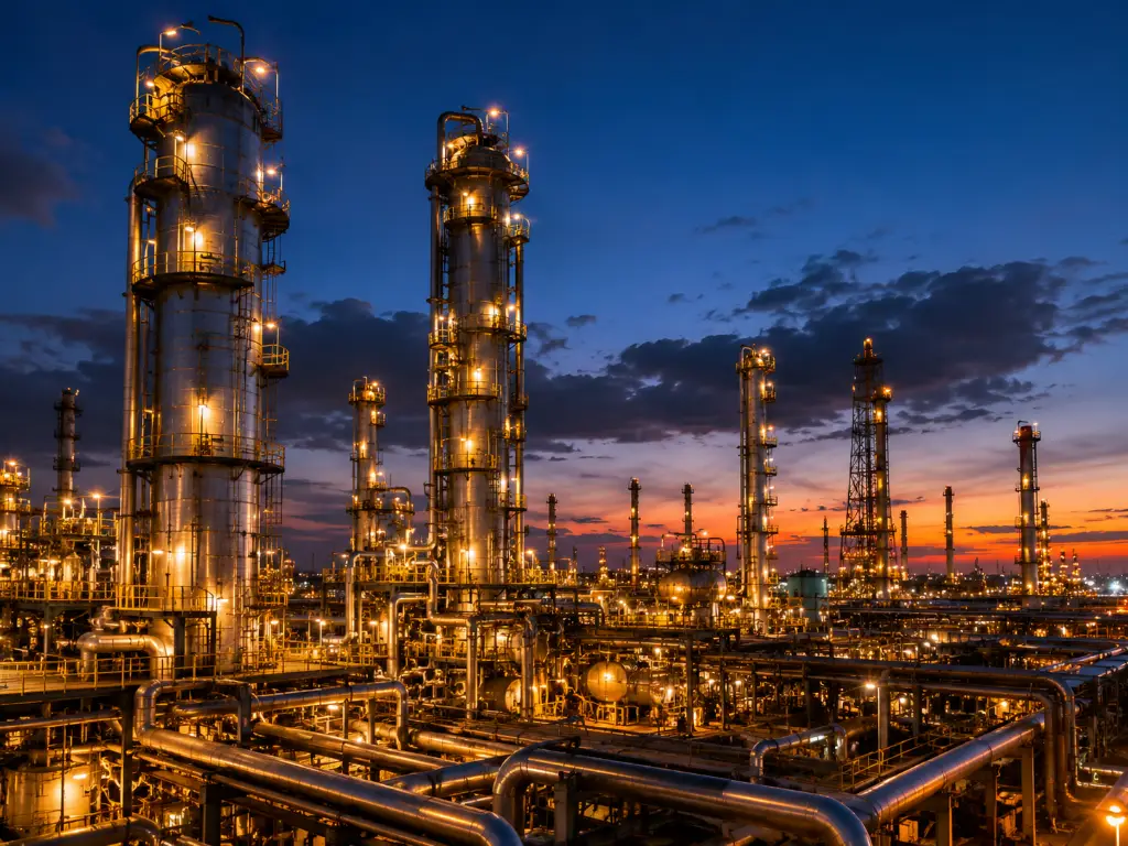
In the midstream energy sector, the term "natural gas processing" refers to the complex sequence of thermodynamic and chemical engineering operations required to transform raw, untreated gas into pipeline-quality, commercial-grade natural gas. To understand the necessity of this infrastructure, we must first look at the fundamental definition of the feedstock. When raw natural gas is extracted from the earth and arrives at the wellhead, it is far from being pure methane. Instead, it is a highly volatile and complex multiphase mixture.
This raw stream typically contains a mixture of light hydrocarbons (methane), heavier Natural Gas Liquids or NGLs (ethane, propane, butane, and pentanes), saturated water vapor (H₂O), highly toxic hydrogen sulfide (H₂S), carbon dioxide (CO₂), inert gases like nitrogen and helium, as well as trace heavy metals like mercury and mechanical impurities such as sand and wellbore fluids.
Processing this multiphase mixture serves two core, non-negotiable objectives in modern plant operations:
- Purification (Conditioning): The primary goal is the strict removal of corrosive, toxic, and non-combustible impurities. This ensures the gas meets universal, highly regulated pipeline tariff specifications. For instance, the Gas Processors Association (GPA) and the American Petroleum Institute (API) generally mandate that sales gas must contain less than 4 ppmv (parts per million by volume) of H₂S, and the CO₂ content must be strictly limited to under 2%. Failure to meet these specs results in pipeline shut-ins and severe metallurgical degradation of the transmission network.
- Separation (NGL Recovery): The secondary, yet economically vital objective, is the extraction of high-value liquid by-products. Ethane, propane, and butane are fundamental building blocks for the global petrochemical industry (used in plastics, refrigerants, and fuels). Separating these NGLs from the bulk methane stream maximizes the economic yield of the processing plant.
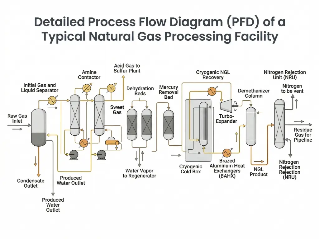
Step 1: Initial Gas and Liquid Separation
The moment the multiphase raw gas stream crosses the battery limits of the processing plant, it enters the initial gas and liquid separation phase. This step acts as the primary physical defense line for all downstream equipment. If bulk liquids and solids are allowed to bypass this stage, they will cause catastrophic foaming in amine contactors, overwhelm dehydration beds, and destroy the aerodynamic balance of downstream compressor impellers.
The working mechanism of this initial phase relies entirely on fluid dynamics, specifically momentum change and gravity settling. By drastically reducing the velocity of the incoming gas stream, the heavier liquid droplets and solid particulates lose their kinetic energy. According to Stokes' Law, once the upward velocity of the gas is lower than the terminal settling velocity of the droplets, the liquids fall out of the gas phase and accumulate at the bottom of the vessel.
Core Hardware Carriers for Initial Separation
To execute this physical separation, engineers rely on massive, high-pressure static vessels:
- Slug Catchers: Gathering pipelines traverse varied topographies, causing liquids to pool in low spots. Periodically, the gas pressure pushes these pooled liquids forward as massive, high-velocity "slugs." Slug catchers are exceptionally high-volume buffering vessels (often built as a series of large-diameter parallel pipes known as harp-type catchers) designed specifically to absorb these massive surges of liquid without overwhelming the plant's steady-state processing capacity.
- 2-Phase and 3-Phase Separators: Once the primary slugs are caught, the gas flows into precision pressure vessels. A 2-phase separator divides gas from total liquids, while a 3-phase separator utilizes gravity specific gravity differences to further separate the liquids into a hydrocarbon phase (condensate) and an aqueous phase (produced water). These vessels are equipped with internal inlet diverters to shatter the momentum of the incoming stream, extensive gravity settling sections to allow phase separation, and highly engineered demister pads (mist extractors made of woven wire mesh or vane packs) at the gas exit nozzle to intercept and coalesce micro-droplets, preventing liquid carry-over into the downstream sweetening units.
Step 2: Acid Gas Removal (Gas Sweetening)
Following initial physical separation, the gas stream—now free of bulk liquids but still containing lethal and corrosive gaseous impurities—moves to the Acid Gas Removal unit. In industry terminology, gas laden with H₂S and CO₂ is referred to as "Sour Gas," while gas stripped of these components is "Sweet Gas."
The process objective here is paramount to plant safety and infrastructure survival. H₂S is not only lethally toxic to personnel at low concentrations but, in the presence of free water, it dissolves to form a weak acid that aggressively attacks carbon steel, causing localized pitting and Sulfide Stress Cracking (SSC). Similarly, CO₂ forms carbonic acid which leads to rapid weight-loss corrosion in pipelines. Furthermore, if CO₂ is not removed, it will freeze solid in the downstream cryogenic liquefaction stages, acting like dry-ice gravel that destroys high-speed rotating machinery.
The primary chemical mechanism employed to sweeten the gas is the Amine Treating process. This relies on an aqueous alkanolamine solvent—most commonly Methyldiethanolamine (MDEA) or Diethanolamine (DEA). The process operates on a continuous absorption and thermal regeneration cycle. In the absorption phase, the cool, high-pressure sour gas flows upward, while the lean (pure) amine solution flows downward. The amine chemically binds with the H₂S and CO₂ molecules. The now "rich" amine (loaded with acid gas) is sent to a low-pressure, high-temperature regenerator column, where heat breaks the chemical bonds, boiling off the acid gases to be sent to a sulfur recovery unit, while the restored lean amine is pumped back to begin the cycle again.
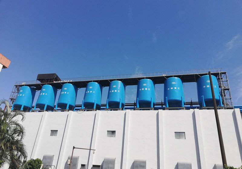
Core Hardware Carrier: Amine Contactors
The heart of this operation is the Amine Contactor (Absorber). These are towering, heavy-walled vertical pressure vessels designed to maximize the mass transfer between the gas and liquid phases. To achieve this, the internals of the contactor are fitted with either fractionation trays (such as valve trays or bubble cap trays) or structured packing. These internals force the rising sour gas to bubble violently through the descending liquid amine, maximizing the counter-current contact area and ensuring the chemical reaction goes to completion.
Crucial Process Output State: It is imperative for process engineers to note the physical state of the gas as it exits the top of the amine contactor. Because the amine solvent is an aqueous solution (often 50% water), the sweet gas leaving the unit is fully water-saturated at the operating pressure and temperature. This introduces a new, critical threat to the system, mandating immediate and highly efficient downstream dehydration.
Step 3: Natural Gas Dehydration Technologies
The water-saturated sweet gas cannot be transported or cooled in its current state. If water vapor is allowed to remain in the gas stream, any subsequent drop in temperature or increase in pressure will cause the water to condense. In high-pressure gas systems, this condensed water reacts with light hydrocarbon molecules (like methane and ethane) to form Natural Gas Hydrates—solid, ice-like crystalline structures. Hydrate plugs can form in seconds, completely blocking pipelines, jamming valves, and causing catastrophic overpressure events. Therefore, dehydration is a non-negotiable step.
However, the dehydration selection logic is not one-size-fits-all. The technology choice strictly depends on the thermodynamic limits and temperature profiles required by the downstream process. Engineers must choose between standard liquid absorption (TEG) for normal pipelines, or solid desiccant adsorption (Molecular Sieves) for ultra-low temperature operations.
Dehydration Selection Matrix: TEG vs. Molecular Sieve
| Dimension / Parameter | TEG (Triethylene Glycol) Dehydration | Zeolite Molecular Sieve Deep Dehydration |
|---|---|---|
| Lowest Water Dew Point Limit | Approx. -50°F (-45°C) | < -150°F (-101°C) / < 0.1 ppmv |
| Downstream Application | Standard commercial pipeline transmission | Cryogenic NGL Recovery, LNG Liquefaction |
| Energy Consumption Profile | Lower (Moderate reboiler duty) | High (Requires high-temp regeneration gas) |
| CAPEX / OPEX | Lower initial CAPEX, moderate OPEX | High initial CAPEX, cyclic operational OPEX |
Hardware Carrier and Desiccant Integrity
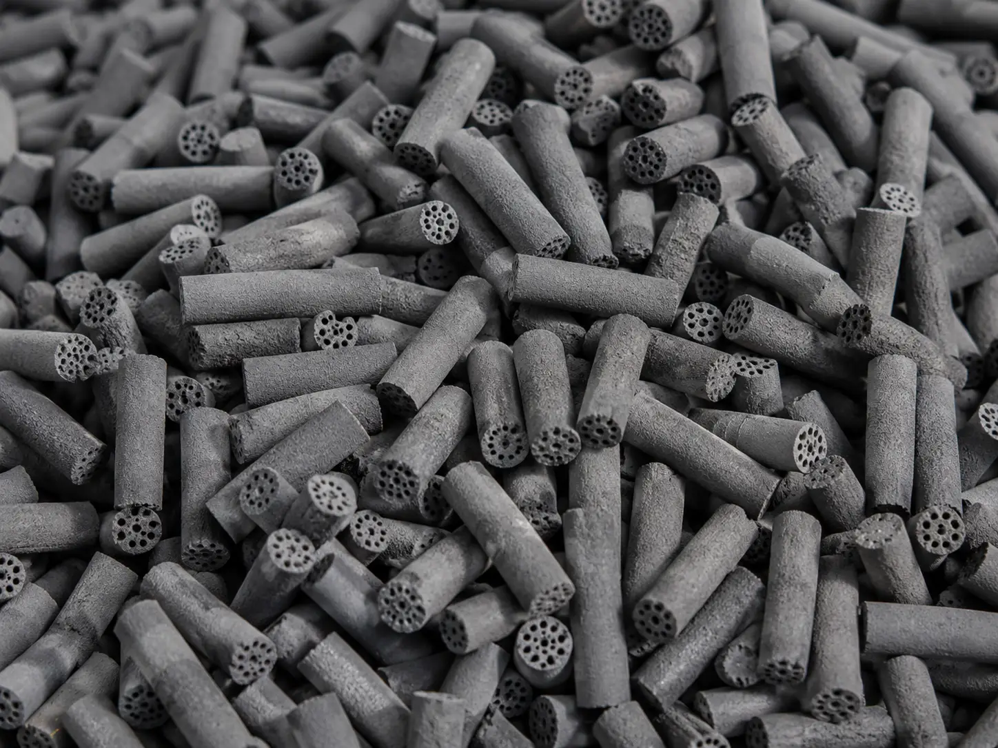
When the plant design calls for deep NGL recovery, TEG systems are thermodynamically incapable of preventing ice formation in the cold box. Instead, the plant must utilize Zeolite Molecular Sieves. These systems rely on solid-state physical adsorption, where water molecules are trapped within the highly uniform microporous crystalline structure of the aluminosilicate zeolite.
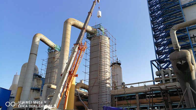
The system hardware for molecular sieve dehydration is massive and highly automated. It features twin-bed or multi-bed adsorber vessels operating in continuous swing cycles. While one vessel is actively on-stream adsorbing water from the high-pressure natural gas, the other vessel is offline undergoing a regeneration phase. This regeneration involves passing a stream of extremely hot, dry residue gas (often heated to 500°F – 600°F via high-temperature regeneration heaters) through the wet bed to vaporize and sweep away the trapped moisture. Once dry, the bed is cooled and placed back on standby. Automated switching valves control this intricate ballet, ensuring the downstream process receives a continuous, uninterrupted flow of bone-dry gas.
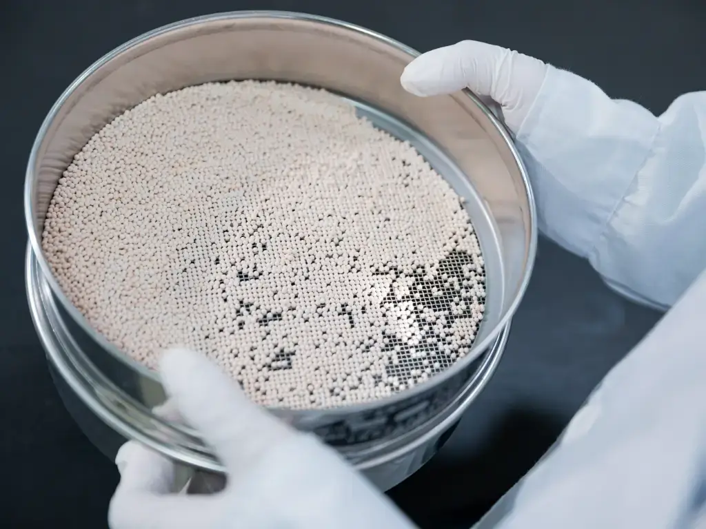
Because these adsorber beds are the ultimate gatekeepers for the natural gas applications downstream, the physical and mechanical constraints of the desiccant itself are of paramount importance. The cyclic nature of the process puts immense strain on the materials.
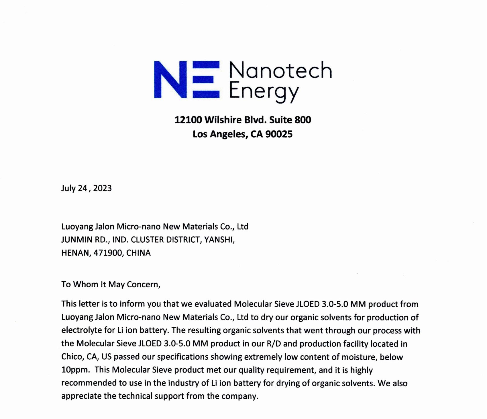
To ensure the mechanical integrity of the dehydration unit and prevent bed degradation, the physical parameters of the desiccant are critical. For instance, JALON's 4A and 13X molecular sieves achieve a high crush strength (e.g., >85 N) and an extremely low attrition rate (<0.1 wt%). Manufactured under strict DCS automation, the resulting uniform particle size and high bulk density allow the bed to withstand the severe mechanical and thermal stresses of thousands of Temperature Swing Adsorption (TSA) cycles without powdering, thereby reliably protecting the downstream cryogenic turbo-expanders.
Step 4: Pre-Cryogenic Mercury Removal
Once the gas is bone-dry, one might assume it is ready for extreme chilling. However, there is a hidden, highly destructive element that must be addressed: trace mercury. Strict process sequencing dictates that Mercury Removal is an absolute prerequisite before the gas is allowed to enter the cryogenic section. If this step is bypassed or improperly placed after the cold box, the financial and safety consequences are devastating.
The chemical hazard posed by mercury lies in a metallurgical phenomenon known as Liquid Metal Embrittlement (LME). Natural gas processing plants utilize aluminum extensively in their cryogenic sections because aluminum actually becomes stronger and more ductile at extremely low temperatures (unlike standard steel, which becomes brittle). However, trace mercury in the gas stream will condense into a liquid at certain temperatures. When liquid mercury contacts the aluminum alloys used in heat exchangers, it rapidly amalgamates with the aluminum, attacking the grain boundaries of the metal. Without removal, mercury will rapidly corrode, weaken, and crack the downstream equipment, potentially leading to catastrophic high-pressure ruptures, explosions, and total plant failure.
To neutralize this threat, engineers utilize highly specialized hardware and chemical mechanisms. The dried gas is routed through fixed-bed pressure vessels packed with sulfur-impregnated activated carbon (or specific transition metal oxide absorbents). As the gas flows through the porous carbon matrix, the elemental mercury vapor undergoes a chemisorption reaction with the impregnated sulfur, forming a highly stable, solid compound known as mercuric sulfide (HgS). This permanently binds and traps the mercury within the bed, ensuring the gas exiting the unit is safe to interface with aluminum metallurgy.
Step 5: Cryogenic NGL Recovery and Fractionation
With the gas now completely stripped of acid gases, dehydrated to sub-ppm moisture levels, and scrubbed of embrittling mercury, it is finally prepared for the harshest thermodynamic environment in the plant: Cryogenic NGL Recovery. The objective here is to chill the gas stream to such extreme sub-zero temperatures that the valuable heavier hydrocarbons (ethane, propane, and butane) lose their gaseous state and condense into collectable liquids, leaving only pure methane gas to be sent to the pipeline.
The thermodynamic mechanism driving this extreme temperature drop is adiabatic expansion. While older plants used Joule-Thomson (J-T) valves to expand the gas, modern high-efficiency plants utilize an isentropic expansion process. By forcing the high-pressure gas to do physical work as it expands, thermal energy is rapidly drained from the gas stream, resulting in a significantly deeper temperature drop than simple valve expansion.
Core Hardware Carriers for Cryogenics
The heart of the NGL recovery process relies on two marvels of mechanical and thermal engineering:
- Turbo-Expanders: These are high-speed rotating machinery units that serve a dual purpose. The high-pressure, pre-cooled natural gas enters the expander turbine, spinning the highly engineered radial impellers at tens of thousands of RPM. As the gas expands and performs this mechanical work, its pressure plummets, and its temperature drops dramatically—often reaching between -120°F and -150°F (-84°C to -101°C). At these temperatures, the NGLs condense and fall out of the gas phase. Furthermore, the mechanical shaft power generated by the expanding gas is transferred across a central shaft to drive a booster compressor on the other side, efficiently re-compressing the lean residue gas for pipeline export.
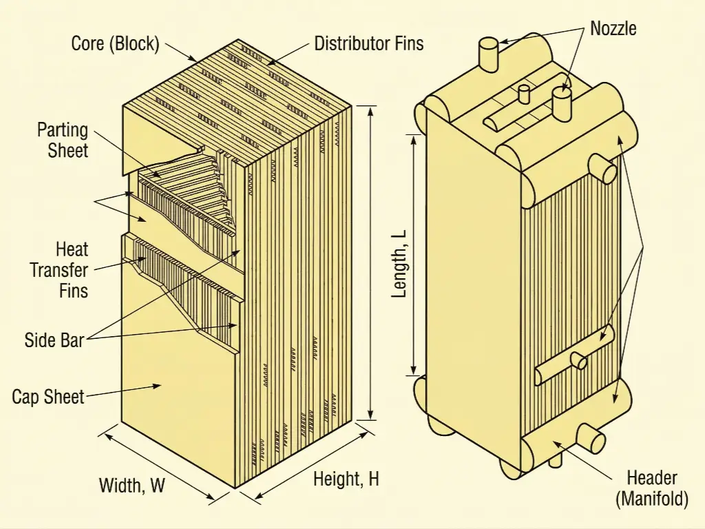
- Brazed Aluminum Heat Exchangers (BAHX): Often referred to as the "Cold Box," these are extremely compact, highly efficient heat transfer units. Constructed from alternating layers of corrugated aluminum fins brazed between flat parting sheets, they offer an unparalleled surface-area-to-volume ratio, facilitating the massive thermal transfer required to pre-cool the incoming gas using the frigid outgoing residue gas. However, their intricate micro-channel design is their greatest vulnerability. Process engineers must recognize that the BAHX strictly relies on the flawless execution of Step 3 and Step 4. If the molecular sieves fail to deliver 0.1 ppmv moisture, the micro-channels will instantly plug with ice and hydrates. If the mercury beds fail, the aluminum fins will disintegrate via LME.
Step 6: Nitrogen Rejection Unit (NRU)
In certain geological reservoirs, raw natural gas is heavily contaminated with nitrogen. While nitrogen is not corrosive or toxic like hydrogen sulfide, it presents a major commercial problem: it is an inert, non-combustible gas. High concentrations of nitrogen act as a diluent, severely reducing the volumetric heating value of the gas stream.
The process objective of the Nitrogen Rejection Unit (NRU) is the targeted removal of this inert gas to ensure the final sales gas meets the minimum British Thermal Unit (BTU) or calorific value specifications legally required by commercial pipeline tariffs. If the BTU value is too low, industrial burners and residential appliances will not operate safely or efficiently, and the gas will be rejected by the transmission company.
Because nitrogen and methane have incredibly low and relatively close boiling points (-320°F and -258°F respectively), separation cannot be achieved through simple absorption. Instead, NRUs rely on complex cryogenic distillation. This is often thermally linked to the tail-gas of the NGL recovery unit. By utilizing specialized cryogenic fractionation columns, the nitrogen is distilled out as an overhead vapor and safely vented to the atmosphere, while the pure, high-BTU methane is recovered from the bottom, compressed, and sent to market.
Plant-Wide Infrastructure & Metallurgical Constraints
A comprehensive understanding of a natural gas processing plant requires recognizing its systemic foundation. While we have detailed the sequential treatment steps, certain critical infrastructure elements span the entire lifecycle of the plant and are not isolated to a single unit. These overarching systems dictate the physical flow and the structural safety of the entire multi-million dollar facility.
Compressor Stations: The Heartbeat of the Plant
Gas does not flow on its own; it requires a pressure differential. Compressor stations act as the driving force of the plant, maintaining systemic hydraulic flow from the wellhead all the way to the final export pipeline. Depending on the volumetric flow rates and required compression ratios, plants utilize either high-speed Centrifugal Compressors (for high volume, continuous flow) or heavy-duty Reciprocating Compressors (for high pressure ratios and varying loads).
Inlet compressors boost the low-pressure gathering lines to the operating pressure of the amine and dehydration units. Booster compressors (often driven by the turbo-expander) help recover pressure lost during processing. Finally, massive residue gas compressors take the fully processed, purified methane and boost it to the 1,000+ PSI required to push the gas hundreds of miles down the commercial transmission pipeline.
Metallurgical & Piping Standards
Process engineers must navigate highly complex and opposing metallurgical constraints across different zones of the plant. A pipe that is perfectly safe in one section could face catastrophic, explosive failure in another.
- Sour Gas Constraints: In the initial separation and amine treating sections (Steps 1 and 2), the piping, valves, and fittings are exposed to wet hydrogen sulfide. Standard carbon steel under high tensile stress will absorb atomic hydrogen, leading to internal blistering and sudden brittle failure. Therefore, all metallurgy in these zones must strictly comply with NACE MR0175 / ISO 15156 standards. This dictates stringent limits on the hardness of the steel (typically restricted to < 22 HRC) and mandates specific post-weld heat treatments to ensure resistance to Sulfide Stress Cracking (SSC).
- Cryogenic Constraints: Conversely, in the NGL recovery and Nitrogen Rejection sections (Steps 5 and 6), the threat is not chemical, but thermal. Standard carbon steel suffers a drastic loss of impact toughness at sub-zero temperatures, undergoing a ductile-to-brittle transition. A minor impact or pressure surge at -150°F can shatter standard steel like glass. Therefore, piping and pressure vessels in the cryogenic sections require specialized Low-Temperature Carbon Steel (LTCS) for moderately cold sections, and highly alloyed Austenitic Stainless Steel (such as 304L or 316L) for the extreme cold box environments to prevent brittle fracture under extreme cold shock.
Ultimately, natural gas processing is a highly interdependent sequence of operations where the success of each phase directly dictates the survival of the next. From initial wellhead separation to deep cryogenic NGL recovery, maintaining strict thermodynamic, chemical, and metallurgical control is the only way to achieve pipeline specifications and maximize overall plant profitability.
Securing Plant Reliability with Superior Desiccant Technology
At JALON, we leverage over two decades of manufacturing expertise to provide the foundational materials that make these extreme processes possible. Our high-performance zeolite molecular sieves are engineered for maximum crush strength, ultra-low attrition rates, and extreme deep dehydration capabilities, ensuring your cryogenic operations run continuously without the threat of hydrate freezing or costly bed degradation.