Understanding the Core Technologies Behind the LNG Production Process
The transformation of natural gas from a volatile subterranean resource into a highly dense, transportable liquid is one of the most remarkable achievements in modern chemical engineering. At its core, the LNG liquefaction process is not merely about cooling a gas; it is a rigorous, multi-stage thermodynamic marathon of purification, extreme refrigeration, and precise pressure management. For engineering, procurement, and construction (EPC) professionals, as well as plant operators, mastering the LNG process is the key to minimizing colossal capital expenditures (CAPEX) and maximizing long-term operational efficiency.
In this comprehensive guide, we will provide a deep dive into the end-to-end LNG production lifecycle. From the meticulous removal of trace impurities that threaten cryogenic infrastructure to the sophisticated thermodynamic refrigeration cycles that pull temperatures down to a staggering −162°C (−260°F), every stage must operate flawlessly. By having the entire LNG process explained in granular detail, decision-makers can better navigate technology selection, equipment procurement, and risk mitigation. Welcome to the ultimate technical breakdown of a modern LNG liquefaction plant.
The End-to-End LNG Production Process
The overarching LNG plant process operates on a strict, sequential physical logic. If any upstream purification phase fails, the downstream cryogenic equipment will suffer catastrophic freezing or metallurgical failure. Here are the six non-negotiable stages of natural gas liquefaction from plant inlet to ship loading.
- Inlet Separation (Condensate Removal): When raw feed gas arrives at the facility from pipelines or directly from the wellhead, it is rarely in a pure gaseous state. It typically contains liquid water, heavy hydrocarbon condensates, and various particulate solids. The very first step requires routing this chaotic mixture through massive inlet slug catchers and multi-phase separator vessels. These physical separators use gravity, impingement, and centrifugal forces to drop out bulk liquids. This initial separation is a critical component of broader natural gas processing, ensuring that the downstream chemical absorption units are not overwhelmed by liquid hydrocarbon foaming or sudden volumetric surges.
- Acid Gas Removal (Sweetening): Raw natural gas inherently contains acid gases, primarily carbon dioxide (CO₂) and hydrogen sulfide (H₂S). In the context of the natural gas liquefaction process, CO₂ is particularly lethal; it sublimates into solid dry ice at −78.5°C (−109.3°F). If allowed into the cryogenic section, this dry ice will instantly block heat exchanger micro-channels. To prevent this, the gas is routed through an amine wash unit. Here, a liquid amine solvent chemically binds with the acid gases in a counter-current contactor column. For a deeper understanding of this vital chemical scrubbing phase, refer to comprehensive resources on CO₂ removal from natural gas and the precise mechanisms behind natural gas sweetening.
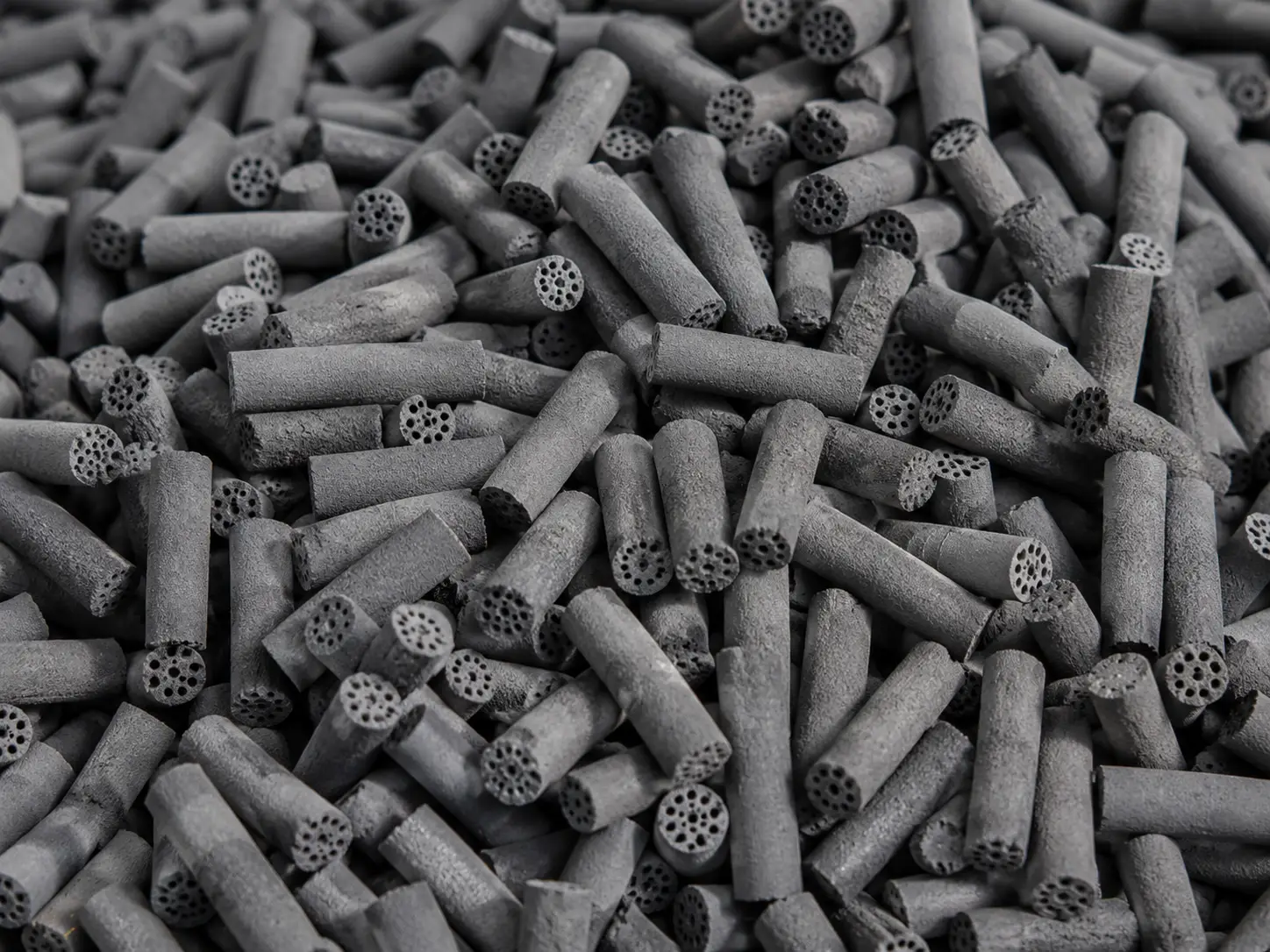
- Deep Dehydration & Mercury Removal: Even after the amine wash, the gas remains saturated with water vapor. Standard pipeline dehydration is insufficient for an LNG cryogenic process. Water freezes at 0°C, and under high pressure, it forms solid hydrate plugs at temperatures well above freezing. The gas must be pushed through Temperature Swing Adsorption (TSA) molecular sieve beds, which physically trap water molecules in microscopic pores, bringing the moisture content down to an extreme limit of < 1 ppm (part per million). Simultaneously, the gas passes through sulfur-impregnated activated carbon or specialized metal oxide beds to permanently strip out trace mercury. Mercury is highly corrosive to aluminum, and even parts-per-billion (ppb) concentrations can destroy the plant's core heat exchangers.
- Heavy Hydrocarbon Fractionation: While methane is the desired end-product, feed gas contains heavier hydrocarbons like ethane, propane, butane, and aromatics like benzene. Benzene freezes at a relatively warm 5.5°C and will create wax-like blockages in the cold box. The gas enters a scrub column or fractionation train where these heavier elements are stripped out. Strategically, this stage is highly lucrative; the extracted ethane and propane are often routed back into the plant to be used as makeup refrigerant for the LNG cooling process, while the remainder is fractionated into Natural Gas Liquids (NGLs) and sold as high-value petrochemical feedstocks.
- Deep Cryogenic Liquefaction: This is the thermodynamic heart of LNG production. The absolutely purified, 100% dry methane enters the heavily insulated cold box. Relying on complex, closed-loop refrigeration cycles, the temperature of the gas is violently pulled down to −162°C (−260°F). As it crosses the boiling point, the methane undergoes a phase change from gas to liquid, accompanied by a volumetric shrinkage of approximately 600 times. This incredible densification is what makes international overseas shipping economically viable.
- Storage and Loading: The newly formed liquid natural gas cannot be stored in standard steel, which becomes as brittle as glass at −162°C. The liquid is piped into specialized, double-walled cryogenic storage tanks. The inner tank is constructed from 9% nickel steel or specialized aluminum alloys, surrounded by meters of perlite insulation. Finally, heavily insulated cryogenic loading arms transfer the liquid into the spherical or membrane tanks of specialized LNG carrier vessels for global export.

Core Liquefaction Technologies & Engineering
The ability to efficiently extract heat from natural gas defines the economic viability of the entire project. There is no single "best" technology; the choice of LNG liquefaction technologies depends heavily on the plant's desired capacity, geographic location, and ambient climate conditions.
Primary Refrigeration Cycles and Decision Matrix
Engineers must carefully evaluate the trade-offs between mechanical complexity, initial capital cost, and long-term thermodynamic efficiency. Below are the primary refrigeration cycles utilized globally.
C3MR (Propane Pre-cooled Mixed Refrigerant)
This is the undisputed workhorse of the industry, dominating roughly 80% of global baseload LNG plants. It utilizes a dual-cycle approach. First, a pure propane (C3) cycle pre-cools the natural gas to about −40°C. Then, a Mixed Refrigerant (MR)—a carefully blended cocktail of nitrogen, methane, ethane, and propane—takes over to drop the temperature to −162°C. It is incredibly thermodynamically efficient and ideal for mega-trains producing over 5 million tonnes per annum (MTPA), though it requires a massive footprint and highly complex piping networks.
SMR (Single Mixed Refrigerant)
Eliminating the propane pre-cooling stage, SMR relies entirely on a single, continuous loop of mixed refrigerant. Because it dramatically reduces the number of compressors, heat exchangers, and associated piping, it offers an exceptionally streamlined flow sheet. While it consumes slightly more specific power than C3MR, its low capital cost and compact footprint make it the premier choice for small-to-medium scale projects, peak-shaving facilities, and offshore Floating LNG (FLNG) vessels.
DMR (Dual Mixed Refrigerant)
Instead of a pure propane pre-cooling cycle, DMR utilizes two separate, independent mixed refrigerant loops. The absolute brilliance of DMR lies in its extreme climate adaptability. Plant operators can dynamically adjust the molecular composition of both refrigerants to match seasonal ambient temperature swings. This makes DMR the technology of choice for environments with brutal temperature extremes, such as the Russian Arctic or deep desert locations.
Cascade Process
One of the earliest but most robust methodologies, the cascade process operates like a thermodynamic relay race. It uses three completely independent, pure refrigerant loops: propane cools the gas to −30°C, ethylene drives it down to −90°C, and finally, a pure methane cycle achieves the final −162°C liquefaction. It boasts extraordinary energy efficiency and operational stability, but the necessity of maintaining three distinct massive compressor strings results in staggering initial capital expenditure (CAPEX).
To assist in technology selection, the following Decision Matrix outlines the optimal operational windows for these LNG liquefaction technologies:
| Technology | Optimal Capacity (MTPA) | Footprint & Complexity | CAPEX vs. OPEX Profile | Best Engineering Use Case |
|---|---|---|---|---|
| C3MR | > 5.0 (Large-Scale) | Very Large / High Complexity | High CAPEX / Low OPEX | Onshore baseload mega-trains requiring maximum energy efficiency. |
| SMR | 0.1 – 3.0 (Small/Mid-Scale) | Compact / Low Complexity | Low CAPEX / Higher OPEX | Peak-shaving plants, modular setups, and offshore FLNG platforms. |
| DMR | 3.0 – 8.0 (Mid/Large-Scale) | Moderate / Moderate Complexity | Medium CAPEX / Low OPEX | Regions experiencing extreme seasonal ambient temperature variations. |
| Cascade | Various (Historically Large) | Extensive / Very High Complexity | Very High CAPEX / Low OPEX | Projects demanding high operational stability with independent cooling stages. |
Four Essential Engineering Frameworks
Supporting these thermodynamic cycles are four distinct engineering disciplines that form the backbone of any LNG liquefaction plant:
Substance Separation & Adsorption Technology
This includes the chemical kinetics of amine absorption for CO₂ removal, the angstrom-level precision of physical adsorption in molecular sieves for dehydration, and the delicate cryogenic distillation columns required for precise NGL fractionation.
Extreme Heat Exchanger Manufacturing
The industry relies on two primary designs capable of surviving massive thermal gradients. Coil Wound Heat Exchangers (CWHE) feature hundreds of kilometers of aluminum tubing meticulously spiraled inside a towering shell. Alternatively, Brazed Aluminum Heat Exchangers (BAHX) use alternating layers of corrugated aluminum fins to achieve massive heat transfer surface areas in highly compact volumes.
Mega-Scale Drive & Compression Technology
Compressing dense refrigerants requires mind-boggling mechanical power. Traditionally, this is achieved using heavy-duty aeroderivative gas turbines that burn natural gas to generate tens of thousands of horsepower. The modern shift, however, is toward massive variable frequency electric motor drives (E-Drive) to power the centrifugal compressors.
Cryogenic Metallurgy & Storage
Engineering materials that do not shatter at −260°F is critical. This dictates the exclusive use of 9% Nickel steel, austenitic stainless steels, and highly specialized aluminum alloys for all piping, valves, and containment vessels downstream of the cooling cycle.
Mission-Critical Equipment in the Liquefaction Loop
When analyzing the CAPEX of LNG gas production, the vast majority of the budget is consumed by three gargantuan pieces of hardware. These physical assets dictate the reliability and daily output of the entire facility.
Main Cryogenic Heat Exchanger (MCHE)
Unquestionably the beating heart of the facility, the MCHE is a towering vertical pressure vessel, often exceeding 50 meters in height and weighing hundreds of tons. Inside, absolutely pure natural gas flows upward through hundreds of kilometers of tightly wound, pencil-thin aluminum tubes. Simultaneously, sub-cooled liquid refrigerants cascade downwards over the exterior of these tubes. Through the thin aluminum walls, the refrigerant aggressively extracts heat from the natural gas, forcing it to condense into a liquid state before exiting the top of the tower.
Refrigerant Compressors
If the MCHE is the heart, the compressors are the muscular system of the LNG process. Once the refrigerant has absorbed heat from the natural gas and vaporized, it must be relentlessly compressed back into a high-pressure state so it can reject its heat to the environment (via air or seawater coolers) and begin the cycle again. These colossal centrifugal or axial compressors operate at extreme rotational speeds and are the absolute largest energy consumers in the entire industrial complex.
The Cold Box
To achieve extreme cryogenic temperatures, preventing ambient heat from leaking into the system is paramount. Engineers integrate multiple Brazed Aluminum Heat Exchangers, cryogenic phase separator vessels, control valves, and intricate piping networks into a massive, structurally reinforced steel casing known as the cold box. The entire void space inside this box is densely packed with granular perlite insulation and continuously purged with dry nitrogen gas. This highly integrated design drastically reduces the plant's physical footprint while creating an impenetrable thermal fortress against ambient heat ingress.
Potential Failures and Critical Operational Risks in LNG Production
Operating a facility at −162°C leaves absolutely zero margin for error. A minor deviation in upstream chemistry or flow dynamics can cascade into catastrophic hardware destruction within minutes. Understanding these risks is paramount for anyone involved in the LNG liquefaction process.
- Freeze-up & Hydrates Plugging: This is the ultimate nightmare for plant operators. If the upstream dehydration molecular sieves fail, or if the amine wash leaves residual CO₂ (> 50 ppm), the consequences are immediate. At cryogenic temperatures, trace water does not just freeze; it forms complex crystalline structures known as natural gas hydrates. Along with solid CO₂ (dry ice), these solids act like industrial blood clots, instantly plugging the microscopic passages of the MCHE. Resolving a severe freeze-up requires a complete plant shutdown and a lengthy, highly expensive thermal defrosting procedure.
- Liquid Metal Embrittlement (LME): Aluminum is the material of choice for cryogenic equipment due to its excellent low-temperature ductility. However, aluminum has a fatal vulnerability: mercury. If the upstream mercury removal guard beds fail, trace amounts of liquid mercury will enter the cold box. The mercury rapidly amalgamates with the aluminum lattice, migrating through the grain boundaries. This Liquid Metal Embrittlement destroys the structural integrity of the metal, causing massive, thick-walled heat exchangers to crack and catastrophically rupture under high pressure, leading to massive explosive hazards.
- Compressor Surge: The giant centrifugal compressors pushing the refrigerants must maintain a specific aerodynamic flow. If there is a sudden drop in feed gas flow, a power dip, or a valve malfunction, the flow of gas through the compressor can reverse. This phenomenon, known as a surge, creates violent, high-frequency aerodynamic hammering. Within seconds, surge conditions can shatter the heavy titanium or steel rotor blades, completely destroying a multi-million-dollar machine and halting production for months.
- Heavy Hydrocarbon Waxing: If the fractionation columns fail to properly strip out heavy aromatic hydrocarbons like benzene, cyclohexane, or pentane, these substances will flow into the deep cryogenic cooling zones. Long before the methane liquefies, these heavy molecules will freeze into dense, sticky, wax-like solids. This wax coats the internal heat transfer surfaces, acting as an insulator, drastically reducing thermodynamic efficiency, and eventually causing severe flow restrictions.
- Tank Rollover and Overpressure: Risks do not end once the LNG is produced. Inside the massive storage tanks, LNG is not a uniform liquid; it consists of different layers with varying densities and temperatures (often due to loading batches from different process trains). If a warmer, denser layer settles at the bottom, it absorbs ambient heat. Eventually, the densities equalize, and the heated bottom layer violently "rolls over" to the surface. This sudden mixing releases a phenomenal, explosive volume of Boil-Off Gas (BOG). If the safety relief valves and BOG compressors cannot handle the sheer volume, the cryogenic storage tank will overpressurize and structurally fail.
Economics, Operations, and Future Horizons
Beyond the nuts and bolts of thermodynamics, the success of an LNG venture is measured in decades of operational profitability and adherence to evolving global environmental standards. Here is how modern operators evaluate and future-proof their assets.
Operational KPIs and BOG Management
- Specific Power Consumption: This is the ultimate Key Performance Indicator (KPI) for any liquefaction facility. It measures exactly how many kilowatt-hours (kWh) of mechanical or electrical energy are required to produce one single tonne of LNG. Because an LNG plant operates continuously for 20 to 30 years, optimizing the heat exchanger pinch points to reduce the Specific Power by even 1% translates to tens of millions of dollars in saved fuel gas or electricity costs over the plant's lifecycle.
- BOG Compression and Management: Liquid Natural Gas is constantly boiling. Even inside the most heavily insulated tanks, ambient heat slowly leaks in, causing a fraction of the LNG to vaporize into Boil-Off Gas (BOG). World-class facilities view BOG not as a nuisance, but as an asset. They employ specialized cryogenic BOG compressors to continuously extract this vapor. The recovered gas is either routed into the fuel gas system to power the plant's own turbines, or it is re-compressed, re-cooled, and re-liquefied, ensuring absolute maximum volumetric yield and preventing tank overpressurization.
Market Shifts: Modularization & E-LNG
- The Modular/Small-scale LNG Revolution: Historically, natural gas liquefaction was dominated by massive, stick-built mega-projects requiring billions in CAPEX and a decade of construction. The industry is currently undergoing a paradigm shift toward modularization. By constructing entire liquefaction trains—including the pre-treatment and SMR cold boxes—as highly compact, skid-mounted modules in controlled shipyards, project timelines are slashed. This "plug-and-play" approach makes it economically viable to monetize small, remote "stranded gas" reserves that could never justify the cost of a traditional pipeline or mega-facility.
- Decarbonization and E-LNG: As global regulatory frameworks demand lower carbon footprints, the traditional method of burning natural gas in massive gas turbines to drive the refrigeration compressors is being phased out. The future is E-LNG (Electrified LNG). By replacing gas turbines with colossal Variable Frequency Drive (VFD) electric motors powered by renewable energy grids, operators can eliminate point-source combustion emissions. Furthermore, modern plants are increasingly integrating Carbon Capture and Storage (CCS) technologies directly into the upstream Acid Gas Removal stage, capturing the raw CO₂ and sequestering it underground to achieve near-zero emission LNG gas production.
In the extreme environment of deep cryogenic liquefaction, absolutely reliable front-end dehydration is the ultimate foundation. As industry experts with over 28 years of profound experience, JALON has engineered specialized molecular sieve products boasting exceptionally high compressive strength and exact pore size control. These desiccants are designed to guarantee a moisture dew point of < 1 ppm, shielding your cold box from catastrophic freeze-ups.