Exploring CO₂ Removal from Natural Gas: Technical Selection between Amine, Membrane, and Adsorption (PSA & TSA)
In the complex landscape of industrial energy, the transition from raw wellhead hydrocarbons to pipeline-grade or cryogenic-grade commodities requires extreme precision. Raw natural gas is rarely suitable for immediate transportation or liquefaction. It is heavily burdened with acid gases, primarily carbon dioxide (CO₂) and hydrogen sulfide (H₂S), alongside water vapor and heavier hydrocarbons. Determining the optimal methodology for CO₂ extraction is not merely a matter of chemical preference; it is a high-stakes economic decision dictated by capital expenditures (CAPEX), operational expenditures (OPEX), space constraints, and the absolute physical limits of downstream processing equipment.
This comprehensive technical guide explores the rigorous engineering premises behind decarbonization and provides an objective, deeply analytical evaluation of the primary technology pathways: Amine Absorption, Polymeric Membranes, and advanced Solid Adsorption techniques utilizing Pressure Swing Adsorption (PSA) and Temperature Swing Adsorption (TSA). By bridging the gap between theoretical thermodynamics and real-world plant operations, we establish a definitive framework for selecting the right gas treatment architecture.
The Engineering Premise: CO₂ Specifications in Natural Gas Processing
The imperative to extract carbon dioxide from natural gas is driven by two distinct tiers of industrial specifications. Understanding the stark contrast between these two targets is the foundational step in process design, as the required depth of removal completely dictates the technology selection.
The first tier consists of standard pipeline specifications. To introduce natural gas into domestic or international transmission grids, regulatory bodies and midstream operators generally impose a CO₂ tolerance limit ranging from 2% to 4% by volume. This requirement exists primarily to maintain the minimum heating value (BTU) of the sales gas and to mitigate severe infrastructural damage. When carbon dioxide dissolves in the presence of free water, it forms carbonic acid (H₂CO₃). This phenomenon, known in the industry as “sweet corrosion,” rapidly deteriorates carbon steel pipelines through aggressive pitting and uniform wall thinning. Over thousands of miles of transmission infrastructure, sweet corrosion can lead to catastrophic pipeline failures, environmental hazards, and astronomical depreciation and replacement costs.
The second tier is vastly more unforgiving: cryogenic processes and Liquefied Natural Gas (LNG) production. When natural gas is processed for deep Natural Gas Liquids (NGLs) recovery, helium extraction, or LNG baseload liquefaction, the temperature of the gas stream is drastically reduced. In an LNG train, temperatures plummet to approximately −161°C (−260°F). At these extreme cryogenic temperatures, a dangerous thermodynamic phase change occurs. Trace amounts of carbon dioxide do not liquefy; instead, they undergo desublimation—transitioning directly from a gas to a solid.
If the CO₂ concentration entering the cryogenic unit exceeds 50 parts per million (ppm), solid dry ice crystals will precipitate out of the gas stream. These solid particles rapidly accumulate within the intricate, micro-channel fin geometries of the Brazed Aluminum Heat Exchangers (BAHX) housed within the cold box. As the passages narrow, the differential pressure (pressure drop) across the heat exchanger spikes exponentially. Ultimately, this results in total physical blockage, forcing an emergency, unplanned plant shutdown. Thawing a cryogenic cold box to remove dry ice blockages incurs millions of dollars in lost production, making the strict adherence to the < 50 ppm CO₂ specification an absolute matter of operational survival.
Essential Pre-treatment Protocols Before Carbon Capture
Before the gas stream ever reaches the primary decarbonization unit—whether it be an amine contactor, a membrane skid, or a molecular sieve bed—it must undergo rigorous physical conditioning. The failure of a CO₂ removal system is rarely a failure of the core technology itself; rather, it is almost always triggered by inadequate upstream natural gas processing that allows liquid carryover to contaminate the sensitive active media.
Knockout Drums and Coalescing Filters for Liquid Removal
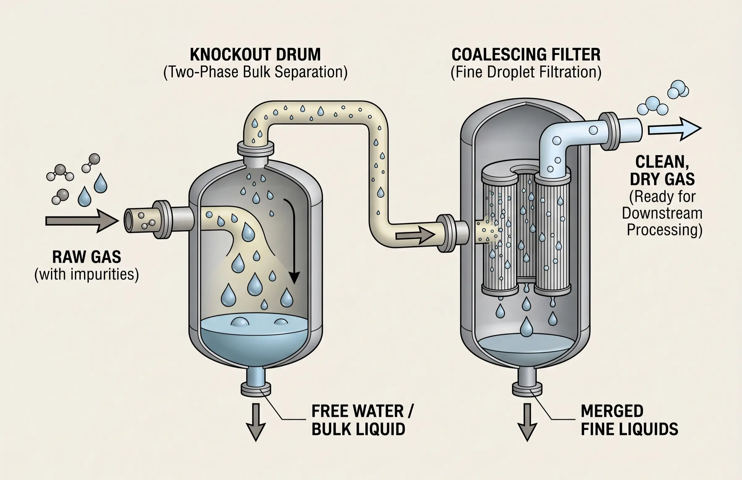
The decisive first line of defense in any gas plant is the inlet separation equipment. Raw natural gas arrives at the facility carrying a multiphase mixture of free water, liquid hydrocarbon condensates, compressor lube oils, and wellbore stimulation fluids. If these liquids are permitted to enter the CO₂ removal unit, the consequences are disastrous.
Inlet knockout drums (two-phase or three-phase separators) utilize gravity, impingement baffles, and centrifugal forces to remove bulk liquids. Following the bulk separation, coalescing filters are deployed to capture micron-sized and sub-micron aerosol droplets. For an amine system, liquid hydrocarbon carryover dramatically lowers the surface tension of the solvent, triggering violent amine foaming. For polymeric membranes, heavy hydrocarbon liquids will coat the membrane surface, permanently fouling the microscopic pores and blinding the separation module. Therefore, robust liquid interception is a non-negotiable physical prerequisite for downstream asset protection.
Temperature Control to Prevent Hydrate Formation
Beyond liquid removal, strict thermal management is required to ensure flow assurance. Natural gas operations frequently involve significant pressure drops, particularly across control valves and chokes. According to the Joule-Thomson effect, a sudden reduction in gas pressure results in a corresponding drop in gas temperature. If the temperature falls below the hydrate formation point in the presence of moisture, water and light hydrocarbon molecules (like methane and ethane) will physically interlock, forming solid, ice-like crystalline structures known as gas hydrates.
Gas hydrates can form at temperatures well above the normal freezing point of water, entirely plugging pipelines, valves, and instrumentation. To counteract this, inlet heaters—such as water bath heaters or direct-fired heaters—are installed upstream of the processing units. By maintaining the feed gas temperature at a safe margin (typically 10°F to 20°F) above the calculated hydrate formation curve, engineers prevent pipeline freezing and ensure a steady, uninterrupted flow into the carbon capture facility.
Quantitative Evaluation of Primary CO₂ Removal Technologies
Process engineers must navigate a complex matrix of operational variables when selecting the appropriate decarbonization route. There is no universal solution; the optimal choice is highly contingent on the raw gas composition, the target purity, available real estate, and utility access. Below is a quantitative evaluation matrix summarizing the performance boundaries of the three primary technologies.
| Process Parameter | Chemical Absorption (Amines) | Polymeric Membrane | Solid Adsorption (TSA/Molecular Sieve) |
|---|---|---|---|
| Ultimate CO₂ Limit | < 50 ppm (with Formulated Amines) | ~2% (Pipeline Spec) | < 1 ppm (Deep Cryogenic Polishing) |
| Equipment Footprint | Extremely Large (Towers, Reboilers, Pumps) | Highly Compact & Modular | Moderate (Multi-bed skids, Heaters) |
| Hydrocarbon Loss (Methane Slip) | Very Low (< 1%) | High (Can exceed 5-10% without multi-stage) | Extremely Low (Selective pore exclusion) |
| Operating Expense (OPEX) | High (Massive thermal reboiler duty, solvent makeup) | Low (Relies on partial pressure differential) | Moderate to High (Thermal regeneration gas heating) |
Amine Gas Treating Systems for Heavy-Duty Processing
For decades, the standard workhorse for acid gas removal in the petrochemical industry has been the amine gas treating system. Operating on the principle of reversible chemical absorption, these systems are engineered to process vast quantities of natural gas, aggressively stripping out carbon dioxide and hydrogen sulfide to meet stringent specifications.
Chemical Absorption Dynamics and Solvent Selection
The operational success of bulk natural gas sweetening hinges entirely on the selection of the correct alkanolamine solvent. The core mechanism involves sour gas flowing upward through a high-pressure, low-temperature absorber column, coming into intimate counter-current contact with a descending stream of lean amine solution. The amine chemically reacts with the acidic CO₂, forming a weak soluble salt, thereby sweetening the overhead gas.
The industry utilizes a spectrum of solvents depending on the exact separation goals. Primary amines, like Monoethanolamine (MEA), are highly reactive and will aggressively remove almost all acid gases, but they require immense thermal energy to break the chemical bonds during regeneration and are highly susceptible to degradation. Secondary amines, like Diethanolamine (DEA), offer a middle ground in reactivity and energy demand. Tertiary amines, specifically Methyldiethanolamine (MDEA), act through a slower base-catalyzed hydration mechanism, allowing them to selectively absorb H₂S while letting a portion of CO₂ slip. For deep LNG pre-treatment requiring < 50 ppm CO₂, engineers frequently turn to “Formulated Amines”—proprietary blends of MDEA with special piperazine activators that dramatically accelerate CO₂ absorption kinetics while minimizing the requisite circulation rates.
Operational Pitfalls Involving Solvent Degradation and Foaming
Despite their ubiquity, amine systems are notoriously temperamental and demand constant operational vigilance. The most severe and costly operational failure is Amine Foaming. When liquid hydrocarbons, well-treating chemicals, or microscopic suspended solids enter the contactor, they alter the surface tension of the amine solution. Instead of flowing smoothly across the column trays, the amine froths into a thick foam. This foam violently expands, flooding the column and carrying unregenerated solvent directly out of the top of the tower alongside the sweet gas—a phenomenon known as massive liquid carryover.
Foaming instantly destroys the separation efficiency, resulting in off-spec gas that must be flared. Furthermore, it results in the physical loss of expensive solvent. Even without foaming, amines undergo continuous thermal degradation from the high temperatures in the reboiler, and chemical degradation from irreversible reactions with oxygen or organic acids, forming Heat Stable Salts (HSS). The ongoing requirement to inject expensive anti-foaming agents and constantly purchase make-up solvent represents a significant, inescapable OPEX burden for the lifetime of the facility.
Polymeric Membrane Separation for Space-Constrained Facilities
When engineering constraints preclude the construction of massive absorption towers, massive solvent inventory, and complex liquid pumping systems, polymeric membrane separation emerges as the premier technological alternative. Unlike amines, membranes involve no moving parts, no hazardous chemical solvents, and no phase changes, representing a purely physical separation process.
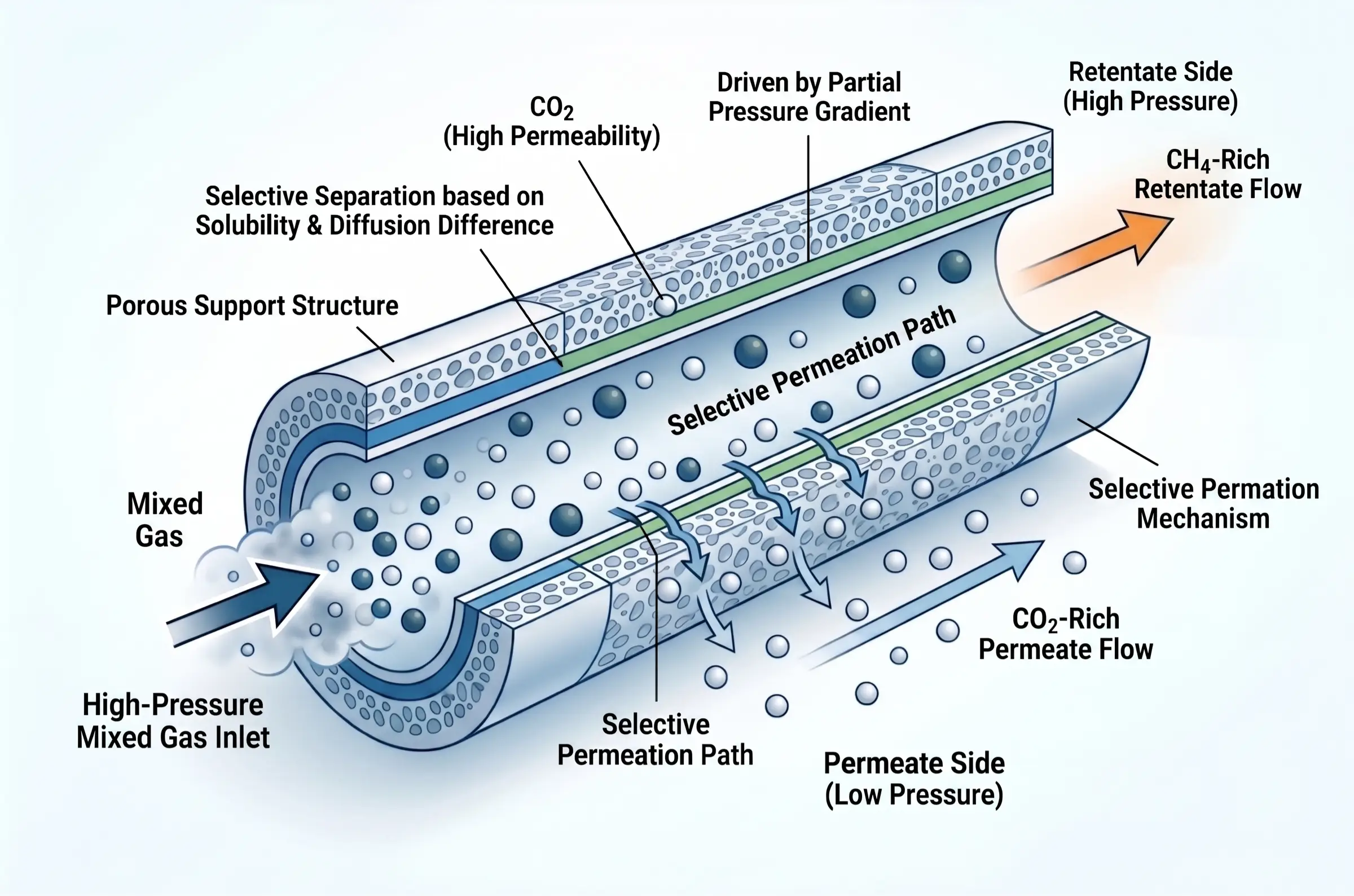
How Permeability and Selectivity Drive Gas Separation
The fundamental driving force behind polymeric membrane separation is the partial pressure differential across the membrane barrier. Raw, high-pressure natural gas is introduced to one side of a hollow fiber or spiral-wound membrane module. The membrane material is engineered at the molecular level to exploit the varying permeation rates of different gas molecules.
Separation is governed by a combination of solubility (how easily the gas dissolves into the polymer matrix) and diffusivity (how fast the molecule travels through the polymer chains). Carbon dioxide is a highly “fast” gas; it is smaller and significantly more soluble in typical polymers than methane. Consequently, CO₂ rapidly permeates through the membrane wall and is collected at a lower pressure on the permeate side, while the slower, larger methane molecules remain retained at high pressure on the retentate side. Because the driving force relies on pressure, this technology thrives in high-pressure offshore environments, subsea tie-backs, and remote wellheads where installing a massive thermal power plant for amine regeneration is physically impossible or economically ruinous.
Overcoming the Threat of Polymer Plasticization
The primary bottleneck limiting the deployment of membranes in highly aggressive gas streams is the phenomenon of membrane plasticization. Polymeric structures are sensitive to highly condensable gases. When a membrane is subjected to natural gas containing exceptionally high concentrations of CO₂ (typically > 10%) or heavy aromatic hydrocarbons (BTEX), these molecules dissolve deeply into the polymer matrix.
This deep dissolution causes the polymer chains to physically swell and relax, effectively softening the membrane. As the polymer plasticizes, the microscopic free volume within the matrix expands, destroying the membrane’s carefully engineered selectivity. With the molecular gates forced wide open, valuable methane easily slips through the membrane alongside the CO₂. This excessive methane slip not only represents a devastating loss of saleable product and revenue but also creates a highly carbon-intensive waste stream that complicates emissions compliance. To mitigate this, engineers must often deploy robust pre-treatment chilling to drop out aromatics, or rely on advanced, rigid glassy polymers that resist plasticization at the cost of overall permeability.
The Adsorption Watershed: PSA for RNG vs. TSA for Cryogenic Polishing
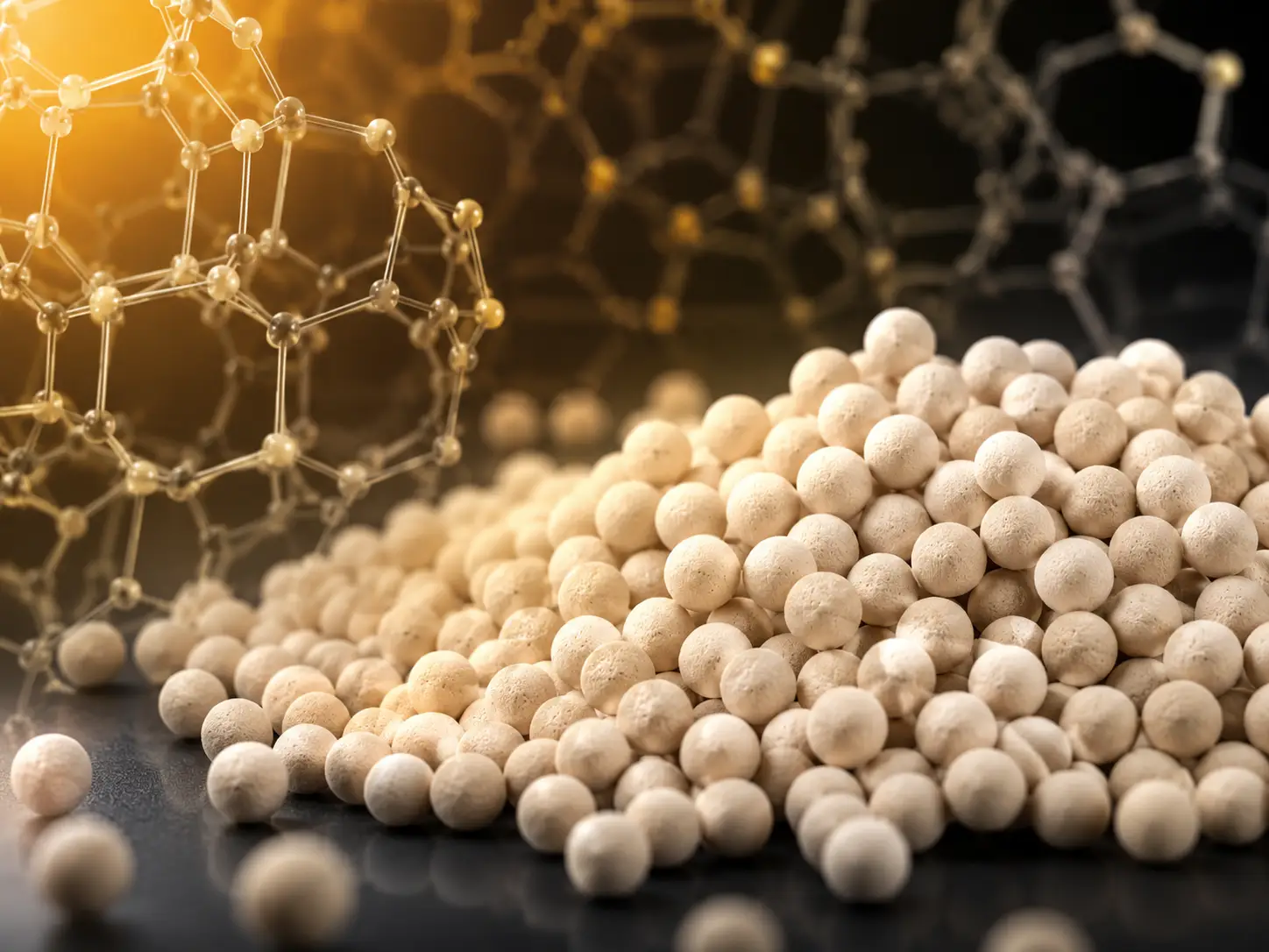
While amine and membrane systems handle the vast majority of bulk decarbonization, the frontier of extreme precision—and the specialized domain of upgrading highly contaminated biogases—belongs to solid adsorption technologies. Utilizing highly engineered, porous aluminosilicate crystalline structures known as molecular sieves, adsorption creates a physical separation watershed governed by pressure and temperature cycles.
Pressure Swing Adsorption (PSA) for Biogas and RNG
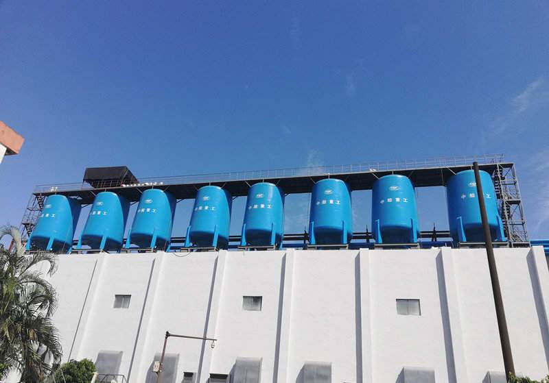
In the rapidly expanding sector of Renewable Natural Gas (RNG) and biogas upgrading, the raw feed gas typically operates at near-ambient temperatures and lower pressures, but contains massive bulk concentrations of CO₂ (often 30% to 50%). Here, Pressure Swing Adsorption (PSA) serves as the ideal bulk removal mechanism. PSA operates on the principle that gases tend to be strongly adsorbed onto solid surfaces under high pressure, and rapidly desorbed (released) when the pressure is dropped to near-atmospheric or vacuum levels.
By cycling multiple vessels packed with specialized adsorbents through sequential phases of high-pressure adsorption, depressurization, low-pressure purging, and repressurization, a PSA unit continuously isolates high-purity biomethane. Because the adsorption binding energy of CO₂ in bulk applications can be overcome simply by swinging the pressure, PSA completely bypasses the massive thermal energy requirements of an amine reboiler, making it exceptionally economical for decentralized biogas facilities.
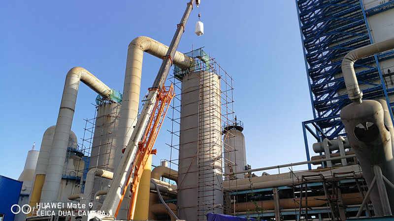
Temperature Swing Adsorption (TSA) for LNG and NGLs Pre-treatment
However, when the objective shifts from bulk removal to deep cryogenic polishing, PSA is physically insufficient. In baseload LNG and deep NGLs recovery plants, the gas leaving the upstream amine unit typically contains around 50 to 500 ppm of CO₂, and it is fully saturated with water. To ensure the absolute survival of the downstream BAHX cold box, both H₂O must be reduced to < 0.1 ppm and CO₂ strictly polished to < 50 ppm. At these trace concentrations, the partial pressure of CO₂ is so low that a simple pressure swing cannot effectively drive the strongly bonded molecules out of the adsorbent pores. The system must utilize Temperature Swing Adsorption (TSA).
In a TSA configuration, the molecular sieve bed adsorbs the trace impurities until it approaches saturation. To regenerate the bed, a slipstream of ultra-dry, heated regeneration gas (typically fired to temperatures between 260°C and 290°C) is passed through the vessel. This intense thermal energy breaks the strong electrostatic bonds holding the polar water molecules and the quadrupolar CO₂ molecules within the sieve framework, thoroughly sweeping the bed clean for the next cycle.
The Jalon Engineering Advantage: Securing the Cryogenic Safety Net
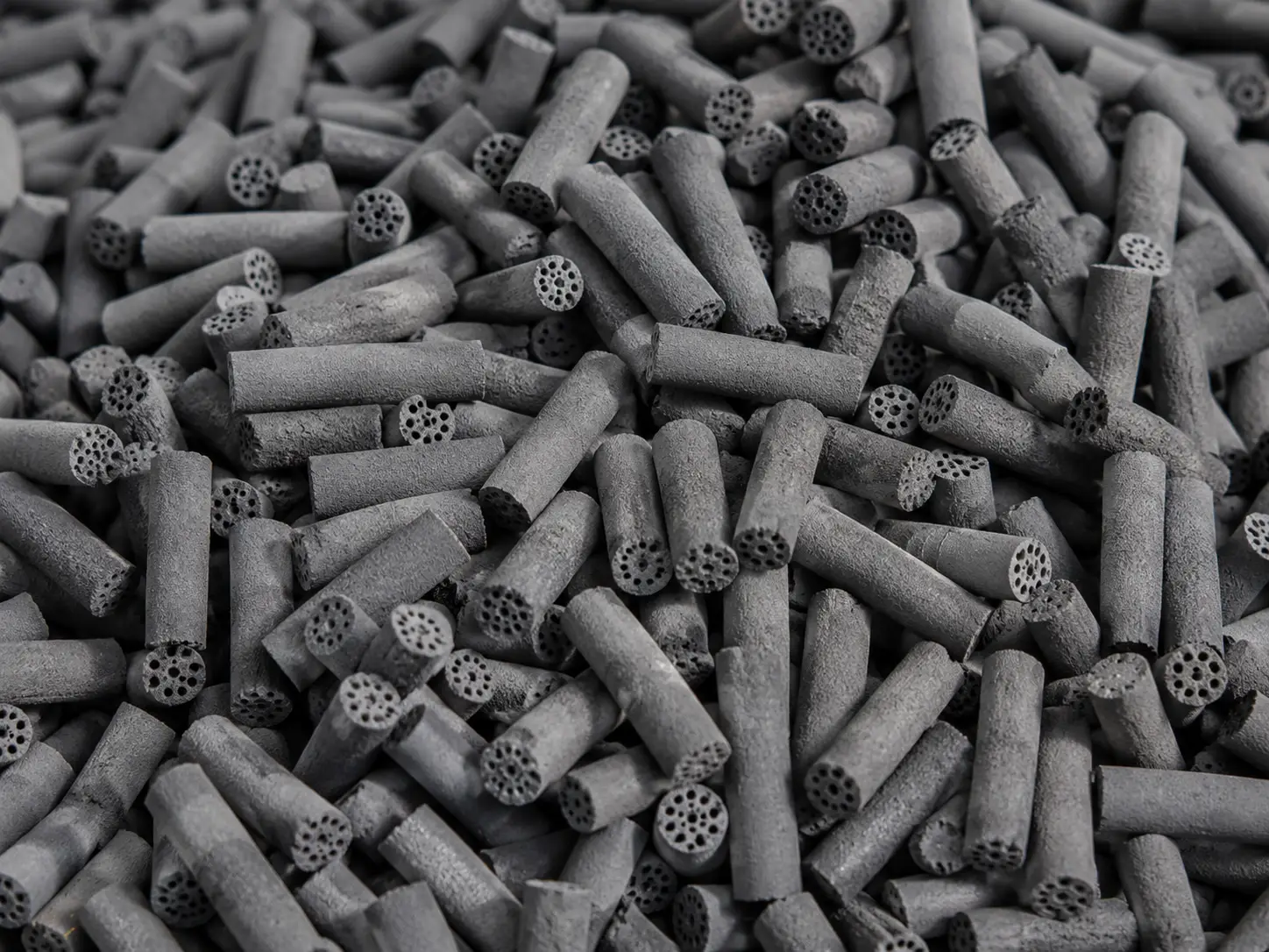
The extreme thermal stresses placed on molecular sieves during TSA regeneration represent the ultimate testing ground for adsorbent durability. Inferior media rapidly succumbs to hydrothermal degradation, losing active surface area, while repeated thermal expansion and contraction cause the beads to physically fracture—a catastrophic failure known as “dusting.” Dusting leads to severe pressure drops, clogged downstream particulate filters, and damaged compressor impellers.
With over 28 years of profound expertise in synthetic zeolites, Jalon’s 13X series and proprietary JLPM series are specifically engineered for the rigors of deep cryogenic air separation and LNG pre-treatment.
- The Fortress of Stability: Utilizing an advanced DCS (Distributed Control System) automated production line with an annual molecular sieve output capacity of 68,000 tons, Jalon entirely eliminates the batch-to-batch variance that plagues standard adsorbents. Plant operators are guaranteed exact, predictable dynamic working capacities across every vessel load.
- Uncompromising Mechanical Integrity: Jalon’s manufacturing process meticulously controls the optimization of inorganic binders and crystallization kinetics, resulting in a molecular sieve with vastly superior Crush Strength. This physical robustness directly combats mechanical attrition and dusting, ensuring that even under the brutal thermodynamic cycling of TSA operations, the media maintains its structural integrity, protecting your downstream cryogenic assets and minimizing OPEX over a prolonged multi-year lifespan.
Standardized Scenarios for CO₂ Removal Technologies
Selecting the optimal decarbonization pathway ultimately requires matching your specific operational constraints with the correct technological framework. Based on decades of process engineering data, we have standardized the technology selection into four definitive operational scenarios.
Chemical Absorption (Amines)
The industry ‘gold standard’ for heavy-duty natural gas sweetening.
- Ideal Flow: > 100 MMSCFD
- CO₂ Range: Moderate to High
- Key Advantage: Massive throughput capacity with < 1% methane slip.
Polymeric Membrane
A purely physical separation module designed for challenging offshore environments.
- Ideal Flow: Variable (Modular)
- Constraint: Severe weight/deck space limits
- Key Advantage: Zero moving parts, no chemical solvents required.
Pressure Swing Adsorption (PSA)
Highly economical bulk removal without the need for massive thermal energy.
- Ideal Flow: < 50 MMSCFD
- CO₂ Range: Ultra-High (20% – 50%)
- Key Advantage: Auto-cycling low OPEX, perfect for biogas upgrading.
Temperature Swing Adsorption (TSA)
The ultimate safeguard utilizing molecular sieves for deep trace removal.
- Target Spec: < 50 ppm CO₂ (Cryo-grade)
- Media: High-performance 13X Zeolite
- Key Advantage: Absolute protection for downstream Brazed Aluminum Heat Exchangers.
For high flow rates (> 100 MMSCFD) facing moderate to high CO₂ concentrations, chemical absorption via formulated amines remains the undisputed heavyweight champion, provided the facility can accommodate the massive physical footprint and thermal utility demands. If that same gas stream is located on an offshore FPSO where deck space and weight load are severely restricted, polymeric membranes emerge as the victor, though operators must accept the economic penalty of elevated methane slip.
When dealing with ultra-high CO₂ concentrations (20% to 70%) typical of Enhanced Oil Recovery (EOR) associated gas, bulk separation often necessitates Cryogenic Distillation (such as CFZ technology), utilizing the phase envelope to freeze out or liquefy CO₂ in a fractionator before polishing.
Ultimately, the decision loop closes at the threshold of cryogenics. Regardless of whether an amine unit or a membrane skid performs the heavy lifting for bulk removal, the uncompromising physics of liquefaction dictate that a Temperature Swing Adsorption (TSA) unit, armed with highly resilient 13X or specialized molecular sieves, must stand guard as the final barrier. By understanding these thermodynamic boundaries and rigorously evaluating the CAPEX, OPEX, and mechanical durability of the selected media, engineers can construct a resilient gas processing facility capable of meeting the stringent demands of the global energy market.